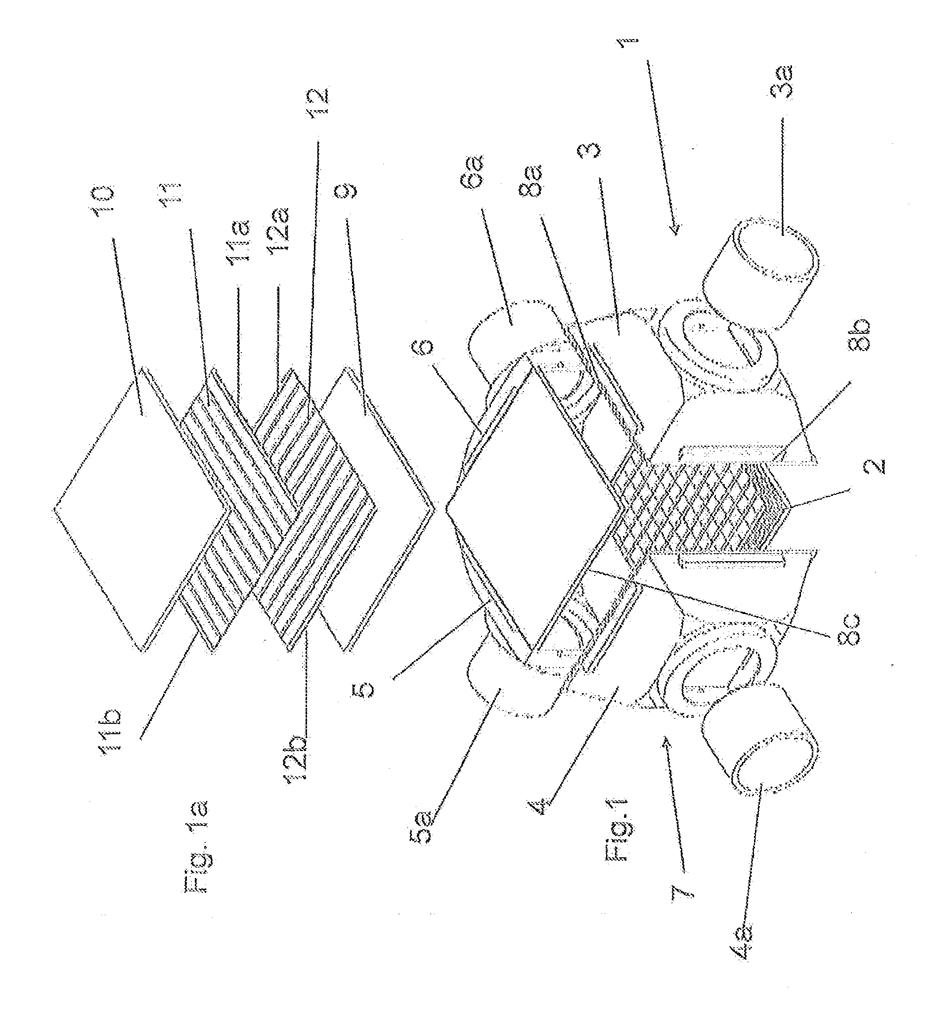
[0010]According to the invention, the layer heat exchanger is characterized by a housing with a
high heat resistance and stiffness, as well as a layer block with a soft and tough core relative to the housing. Compared with the layer block, the housing thereby forms a relatively stiff counter support, which based on its novel design is capable, particularly at high temperatures, of absorbing thermally induced expansion forces originating from the layer block. Based on this firm counter support, the soft and tough core of the layer block will deform elastically or also plastically in part, which is taken into account. It turned out surprisingly that the internal leakage of the layer heat exchanger of the invention is much lower than in the aforementioned prior art layer heat exchangers. The internal leakage arises during operation, e.g., during use of the heat exchanger in the periphery of a high-temperature fuel
cell because gas that has a temperature of 900 to 950° C. encounters the cold layer block during a
cold start. The
thin layer plates heat more rapidly than the thicker housing material, so that because of the thus predefined
thermal expansion ε of the plates, according to Hook's law, a force F˜E·ε (E=elasticity modulus) on the housing arises. When the housing of the invention opposes the force exerted by the plates with a sufficiently
high heat resistance, the layer plates in the interior (of the layer block) are more likely to deform elastically or plastically and thereby to reduce the force. It is accepted in this case that the layer plates in the interior may be damaged with often repetition of the
cold start; i.e., a relative internal leakage is permitted according to the invention. It is advantageous that the damage is limited locally, namely, to regions that reach the highest temperatures. This limits the internal leakage. The extent to which an internal leakage forms during operation depends on the selection of the materials, particularly the material of the layer plate. The external tightness is absolutely assured, however; i.e., the escape to the outside of gas that has a temperature of 950° C. and may also contain
hydrogen is prevented in each case.
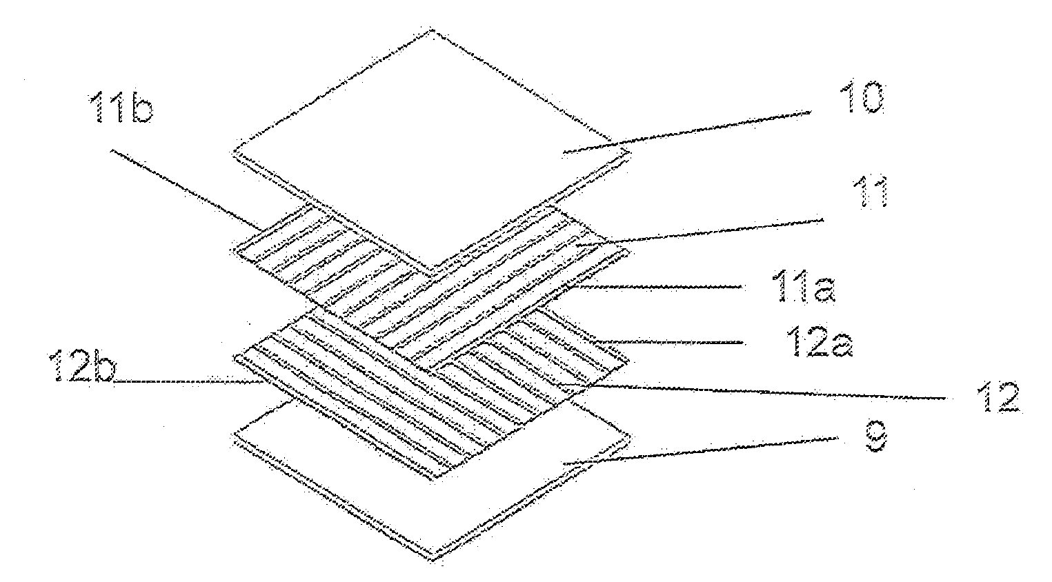
[0014]According to another embodiment, the cover and layer plates are made of a material that has a lower
heat resistance compared with the material of the housing, particularly a low hot yield strength σ0.2. By means of this
pairing of materials with a different
heat resistance for the housing, on the one hand, and the layer block, on the other, the aforementioned expansion behavior of the layer block is achieved at high temperature stresses; i.e., a sufficient internal tightness and a complete external tightness are assured.
[0020]According to an embodiment, the wall thickness of the housing is about 1.5 mm and that of the layer plates about 0.3 mm. The wall thickness of the housing material, in contrast to the wall thickness of the layer and cover plate material, can be relatively low, when the
heat resistance of the housing material is high relative to the heat resistances of the layer plate material. It is especially preferable accordingly when the housing material consists of a high-temperature-resistant material with a low thickness such as, for example, 2.4856 with a 1.0 mm or 0.5 mm wall thickness and the layer and / or cover plate material of a soft material such as the aforementioned FeCrAl alloys. The especially minor difference in
mass between the housing, on the one hand, and the layer and cover plates, on the other, leads to especially low thermal stresses. An
Al content of ≧2%, especially preferably ≧3% is especially useful in this case.
[0021]According to another embodiment, it is provided alternatively or cumulatively that the layer and cover plates are connected to one another by bonding only on the front side at their sealing edges, preferably by
soldering or
welding. Ribs or nubs, which are located in the interior of the heat exchanger or lead from the outside into the interior of the heat exchanger, should thereby not be connected to one another by bonding or at least to the lowest extent possible. The
advantage is achieved thereby that the layer block is securely sealed toward the outside and remains soft and elastically deformable in the interior in its core.
[0024]The use of the layer heat exchanger of the invention proves to be advantageous particularly in the periphery of a high-temperature fuel
cell, preferably in motor vehicles, to meet the strict conditions applicable there in regard to an internal and external tightness of the heat exchanger.

