Method of Making Axial Alignment of Charged Particle Beam and Charged Particle Beam System
a technology of charged particle beam and axial alignment, which is applied in the direction of material analysis using wave/particle radiation, instruments, nuclear engineering, etc., can solve the problems of operator, large burden on operator, etc., and achieve the effect of easy making axial alignment of charged particle beam
- Summary
- Abstract
- Description
- Claims
- Application Information
AI Technical Summary
Benefits of technology
Problems solved by technology
Method used
Image


Examples
first embodiment
1. First Embodiment
1.1. Configuration of Charged Particle Beam System
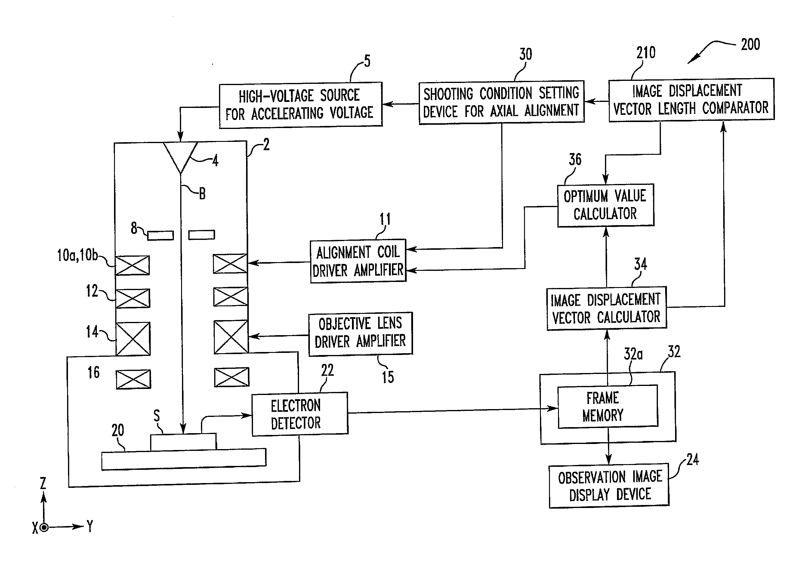
[0092]First, the configuration of a charged particle beam system associated with the present embodiment is described by referring to FIG. 1. The system is generally indicated by reference numeral 100 and is a scanning electron microscope (SEM).
[0093]As shown in FIG. 1, the charged particle beam system 100 includes a charged particle beam source 4, a high-voltage source 5 for producing an accelerating voltage, an objective aperture 8, a first alignment coil 10a, a second alignment coil 10b, an alignment coil driver amplifier 11, an aperture angle correcting lens 12, an objective lens 14, an objective lens driver amplifier 15, scan coils 16, a sample stage 20, an electron detector 22, an observed image display device 24, a shooting condition setting device 30 for axial alignment, a storage device 32 (including a frame memory 32a), an image displacement vector calculator 34, and an optimum value calculator 36.
[0094]Fo...
second embodiment
2. Second Embodiment
[0140]A method of making axial alignment of a charged particle beam implemented in a charged particle beam system associated with a second embodiment of the present invention is next described. Since the charged particle beam system associated with the second embodiment is similar in configuration with the charged particle beam system 100 already described in connection with FIG. 1, its description is omitted. Similarly, charged particle beam systems associated with third through sixth embodiments (described later) are similar in configuration with the charged particle beam system 100 already described in connection with FIG. 1 and so their description is omitted.
[0141]FIG. 8 is a diagram illustrating first through third image displacement vectors associated with the present embodiment.
[0142]In the first embodiment, the fourth image displacement vector V (q, r) is computed from the frames 1 and 7. The fifth image displacement vector U (m, n) is calculated from th...
third embodiment
3. Third Embodiment
[0146]A method of making axial alignment of a charged particle beam in a charged particle beam system is next described, the method being associated with a third embodiment of the present invention.
[0147]In the present embodiment, by setting equal the incremental amounts AL1 and AL2 by which the excitation currents in the alignment coils 10a and 10b are incremented or decremented, the frames 3 and 7 are made the same image. Also, the frames 5 and 8 are made the same image. In consequence, the optimum values X3 and Y3 of the excitation currents in the alignment coils 10a and 10b can be calculated from 6 images (frames 1 to 6).
[0148]More specifically, the image displacement vector calculator 34 calculates the fourth image displacement vector V from the amount of positional deviation between the frames 1 and 3 and the fifth image displacement vector U from the amount of positional deviation between the frames 1 and 5. Subsequent computations are the same as in the fi...
PUM
 Abstract
Description
Claims
Application Information
 - R&D
- Intellectual Property
- Life Sciences
- Materials
- Tech Scout
- Unparalleled Data Quality
- Higher Quality Content
- 60% Fewer Hallucinations
Browse by: Latest US Patents, China's latest patents, Technical Efficacy Thesaurus, Application Domain, Technology Topic, Popular Technical Reports.
© 2025 PatSnap. All rights reserved.Legal|Privacy policy|Modern Slavery Act Transparency Statement|Sitemap|About US| Contact US: help@patsnap.com