
Voltage detection circuit

Inactive Publication Date: 2012-06-07
HONG FU JIN PRECISION IND (SHENZHEN) CO LTD +1
View PDF9 Cites 2 Cited by
  • Summary
  • Abstract
  • Description
  • Claims
  • Application Information

AI Technical Summary

Problems solved by technology

When a power supply unit, such as a battery of a computer motherboard, cannot supply enough voltage to the computer motherboard, the computer motherboard may not work normally.

Method used


Image

  • Voltage detection circuit
  • Voltage detection circuit

Examples


Embodiment Construction

[0007]The disclosure, including the accompanying drawing, is illustrated by way of example and not by way of limitation. It should be noted that references to “an” or “one” embodiment in this disclosure are not necessarily to the same embodiment, and such references mean at least one.

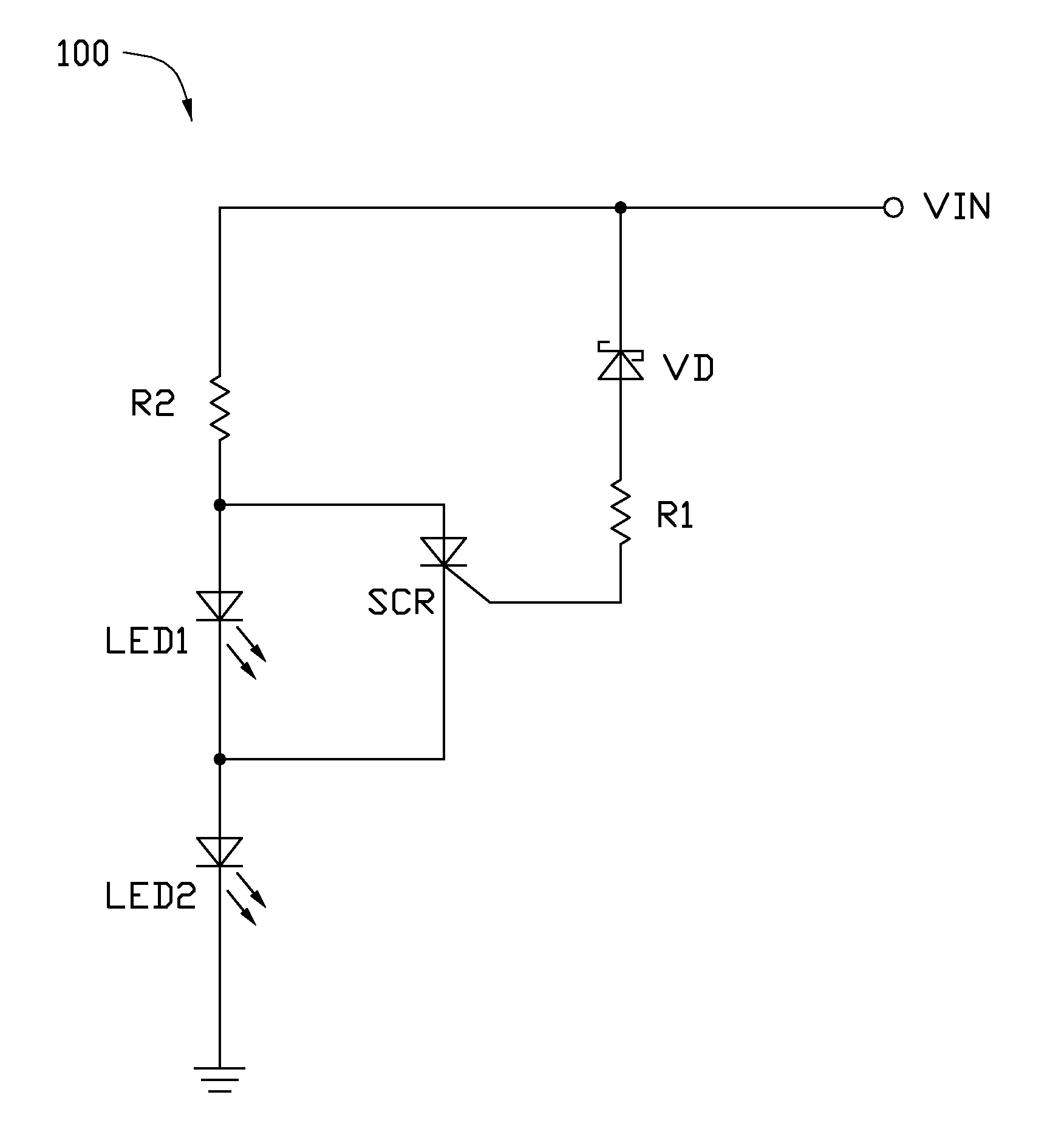
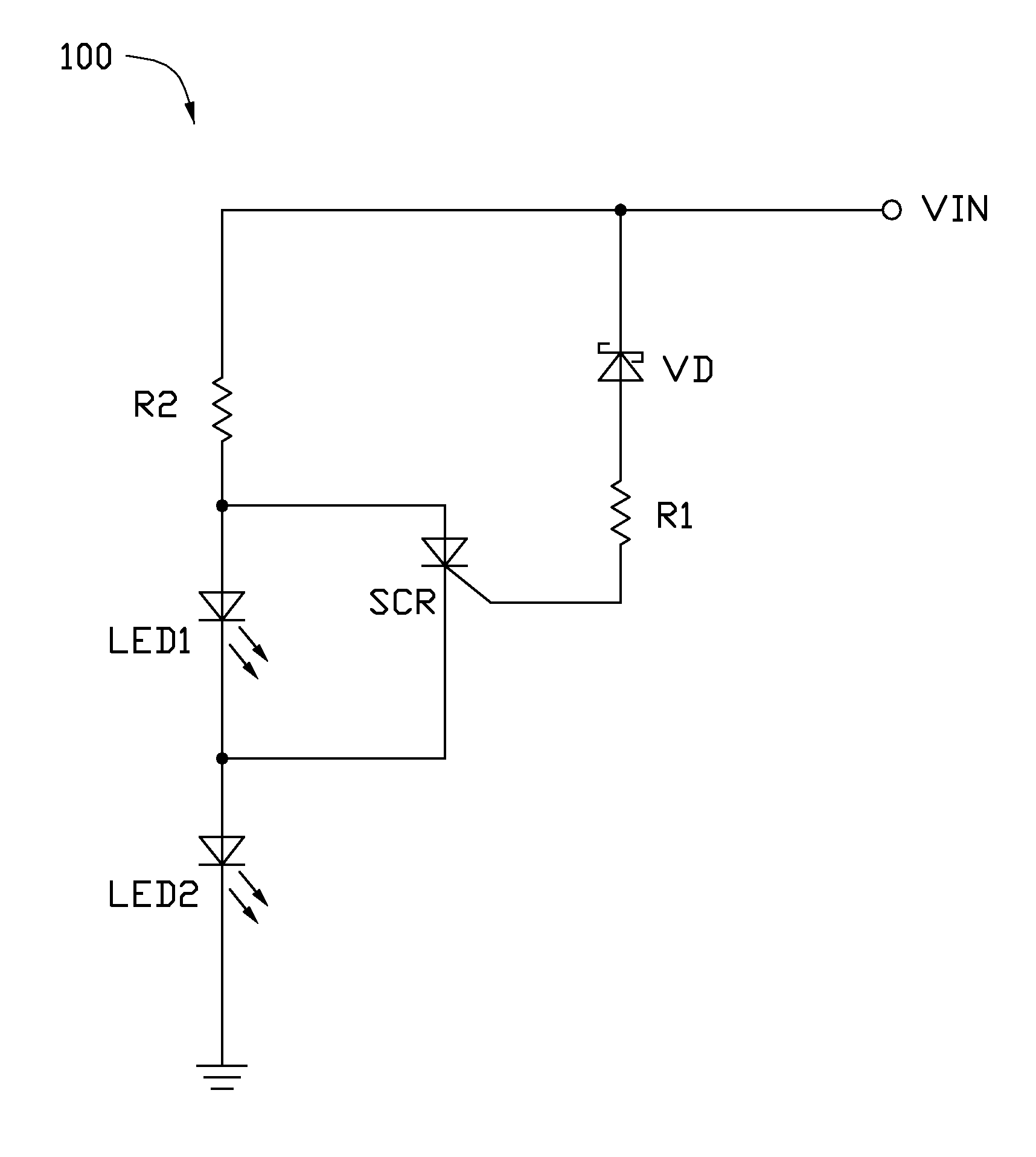
[0008]Referring to the drawing, an embodiment of a voltage detection circuit 100 is used to detect a voltage source VIN of an electronic device. The voltage detecting circuit 100 includes a Zener diode VD, a thyristor SCR, a first light-emitting diode LED1 (hereinafter first diode LED1), a second light-emitting diode LED2 (hereinafter second diode LED2), and two resistors R1 and R2.

[0009]A cathode of the Zener diode VD is connected to the voltage source YIN. An anode of the Zener diode VD is connected to a control terminal of the thyristor SCR through the resistor R1. An anode of the thyristor SCR is connected to an anode of the first diode LED1, and connected to the voltage source VIN through the resis...


PUM


Abstract

A voltage detection circuit used to detect a voltage source includes a Zener diode, a thyristor, a first resistor, a second resistor, a first light-emitting diode (LED), and a second LED. A cathode of the Zener diode is connected to the voltage source. An anode of the Zener diode is connected to a control terminal of the thyristor through a first resistor. An anode of the thyristor is connected to the voltage source through a second resistor. The anode of the thyristor is connected to an anode of the first LED. A cathode of the thyristor is connected to a cathode of the first LED. The cathode of the thyristor is connected to an anode of the second LED, and a cathode of the second LED is grounded.

Description

BACKGROUND[0001]1. Technical Field[0002]The present disclosure relates to a voltage detection circuit.[0003]2. Description of Related Art[0004]When a power supply unit, such as a battery of a computer motherboard, cannot supply enough voltage to the computer motherboard, the computer motherboard may not work normally. Therefore, a voltage detecting circuit for detecting voltage level is needed.BRIEF DESCRIPTION OF THE DRAWING[0005]Many aspects of the present embodiments can be better understood with reference to the following drawing. The components in the drawings are not necessarily drawn to scale, the emphasis instead being placed upon clearly illustrating the principles of the present embodiments.[0006]The drawing is a circuit diagram of an embodiment of a voltage detection circuit.DETAILED DESCRIPTION[0007]The disclosure, including the accompanying drawing, is illustrated by way of example and not by way of limitation. It should be noted that references to “an” or “one” embodim...

Claims


Application Information

Patent Timeline
IPC IPC(8): G01R19/00G01R31/40
CPCG01R19/16542G01R19/16523
Inventor HUANG, YONG-ZHAO
Owner HONG FU JIN PRECISION IND (SHENZHEN) CO LTD
Learn More