Voltage detection device for assembled battery

a voltage detection and battery technology, applied in measurement devices, instruments, scientific instruments, etc., can solve the problems that a low-voltage process such as a 5v system or a 3.3v system cannot be employed in these voltage detection circuits, and the manufacturing cost of the voltage detection circuit may increas

Active Publication Date: 2012-06-07
DENSO CORP
View PDF1 Cites 28 Cited by
  • Summary
  • Abstract
  • Description
  • Claims
  • Application Information

AI Technical Summary

Benefits of technology

[0007]In view of the foregoing and other problems, it is an object of the present invention to produce a voltage detection device, without a high-voltage transistor, for an assembled battery.
[0008]According to an aspect of the present invention, a voltage detection device for an assembled battery including a plurality of unit batteries connected in series, the voltage detection device being configured to detect a voltage of each of the unit batteries of the assembled battery, the voltage detection device comprises an operational amplifier having an input terminal biased at a predetermined reference voltage. The voltage detection device further comprises first capacitors provided respectively to the unit batteries. The voltage detection device further comprises first switch devices each provided between a high-voltage-side terminal of corresponding one of the unit batteries and one end of corresponding one of the first capacitors. The voltage detection device further comprises second switch devices each provided between a low-voltage-side terminal of corresponding one of the unit batteries and the one end of corresponding one of the first capacitors. The voltage detection device further comprises third switch devices each provided between an inverting input terminal of the operational amplifier and an other end of corresponding one of the first capacitors. The voltage detection device further comprises a second capacitor and a fourth switch device provided in parallel between the inverting input terminal of the operational amplifier and an output terminal of the operational amplifier. The voltage detection device further comprises a control unit configured to detect the voltage by implementing the following first and second processes in order: the first process to: open both the second switch devices and the third switch devices corresponding to the unit batteries excluded from an object of voltage detection, close the fourth switch device, and close both one of the first switch devices and one of the third switch devices corresponding to one of the unit batteries being an object of voltage detection to charge corresponding one of the first capacitors; and the second process to: open the fourth switch device, and close one of the second switch devices corresponding to the one of the unit batteries being the object of voltage detection, instead of the one of the first switch devices.
[0009]According to another aspect of the present invention, a voltage detection device for an assembled battery including a plurality of unit batteries connected in series, the voltage detection device b

Problems solved by technology

However, semiconductor switch devices employed in these voltage detection circuits are applied with still high voltage.
Therefore, a low-voltage process, such

Method used


Image

  • Voltage detection device for assembled battery
  • Voltage detection device for assembled battery
  • Voltage detection device for assembled battery

Examples


first embodiment

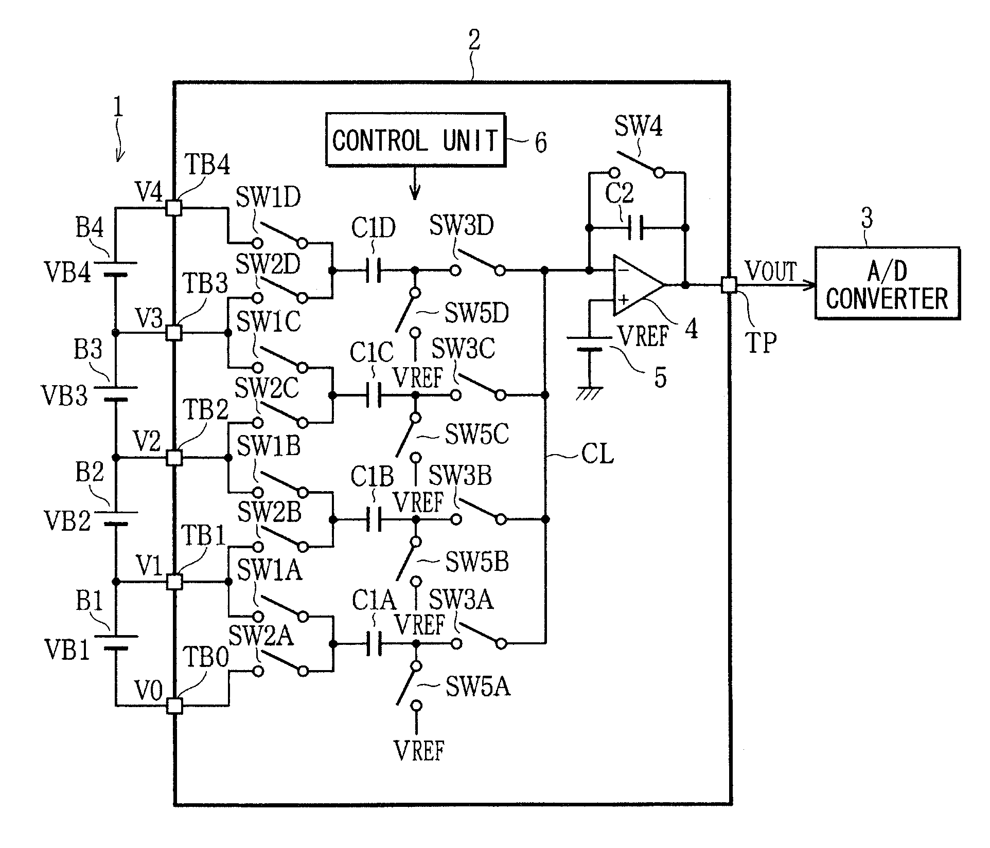
[0025]As follows, the present embodiment will be described with reference to FIGS. 1 to 6. FIG. 1 shows a configuration of a voltage detection device for an assembled battery. The assembled battery 1 is equipped in a hybrid vehicle or an electric vehicle and configured to supply electricity to an electric motor through an inverter. An actual assembled battery 1 includes, for example, a large number of lithium secondary batteries, a nickel hydride secondary batteries (unit batteries), and the like connected in series. In the present example, a battery cell B1 on the low-voltage side to a battery cell B4 on the high-voltage side are shown in consideration of convenience of explanation.

[0026]The battery cells of the lithium secondary battery may vary in the charging state (state of charge: SOC) and the cell voltage due to individual difference in capacity of the battery cells, difference in the self-electric discharge characteristic of the battery cells, and the like. In such an assemb...

second embodiment

[0056]Subsequently, the second embodiment will be described with reference to FIGS. 7, 8. In the voltage detection device 31 according to the present embodiment, the configuration of the fourth switch device is modified, compared with that of the first embodiment in order to eliminate influence of the offset voltage of the operational amplifier 4. The fourth A switch device SW4A is connected between the inverting input terminal of the operational amplifier 4 and the output terminal of the operational amplifier 4. In addition, a series circuit including the second capacitor C2 and the fourth B switch device SW4B is connected in parallel with the fourth A switch device SW4A. The fourth C switch device SW4C is connected between the common connection point, which is between the second capacitor C2 and the fourth B switch device SW4B, and the voltage line applied with the constant voltage VA. The control circuit 6 controls regularly the fourth A switch device SW4A and the fourth C switch...

third embodiment

[0065]Subsequently, the third embodiment will be described with reference to FIGS. 9 to 11. The voltage detection device 41 of the present embodiment employs the operational amplifier 42 having a differential output configuration. In the present embodiment, the voltage detection device 31 of the second embodiment is modified to have a fully-differential-type configuration. The common voltage VCOM of the operational amplifier 42 is set to be equal to the reference voltage VREF. The operational amplifier 42 outputs differential voltages VOP, VOM respectively from the noninverting output terminal and the inverted output terminal. The differential voltages VOP, VOM outputted from the output terminals TP, TM are converted by the A / D conversion device 43 having a of difference input configuration into digital data.

[0066]The circuit of the operational amplifier 42 on the side of the inverting input terminal and the noninverting output terminal and the circuit of the operational amplifier 4...


PUM


Abstract

An operational amplifier has an input biased at a predetermined reference voltage. A control unit opens both second switches and third switches corresponding to unit batteries being non-detection object, closes fourth switch. The control unit further closes both one of first switches and one of third switches corresponding to one unit battery being a detection object to charge corresponding one of first capacitors. Thereafter, the control unit opens the fourth switch. The control unit further closes one of the second switches corresponding to the one unit battery being the detection object, instead of the one of the first switches. Thus, the control unit detects a voltage of each of the unit batteries.

Description

CROSS REFERENCE TO RELATED APPLICATIONS[0001]This application is based on and claims priority to Japanese Patent Application No. 2010-270262 filed on Dec. 3, 2010, the contents of which are incorporated in their entirely herein by reference.TECHNICAL FIELD[0002]The present invention relates to a voltage detection device for an assembled battery including multiple unit batteries connected in series, the voltage detection device being configured to detect the voltage of each unit battery of the assembled battery.BACKGROUND[0003]A hybrid vehicle or an electric vehicle is equipped with an assembled battery including multiple secondary batteries (unit batteries) connected in series. In such an assembled battery, it is necessary to detect the voltage of each secondary battery cell individually for calculating the capacity of each secondary battery cell and protection management of the secondary battery cell. It is noted that an assembled battery for such an application includes a signific...

Claims


Application Information

Patent Timeline
IPC IPC(8): G01N27/416
CPCG01R19/16542G01R31/3658G01R31/362G01R31/396G01R31/3835
Inventor MAKIHARA, TETSUYA
Owner DENSO CORP
Why Eureka
Try Eureka