
Annular gas turbine housing component and a gas turbine comprising the component

a gas turbine and housing technology, applied in the direction of machines/engines, stators, liquid fuel engines, etc., can solve the problems of limited flow speed, which would otherwise be necessitated, and achieve the effect of increasing the flow speed

Inactive Publication Date: 2012-06-07
VOLVO AERO CORP
View PDF5 Cites 6 Cited by
  • Summary
  • Abstract
  • Description
  • Claims
  • Application Information

AI Technical Summary

Benefits of technology

[0005]There is a desire for improved performance and fuel efficiency in turbofan and other turbine engines. Specific thrust may be increased and specific fuel consumption may be decreased by increasing the cycle pressure ratio (CPR) of the engine. One known way of increasing the CPR beyond today's level is to cool the incoming air between the compressor stages. The annular gas turbine housing component may be arranged between the low pressure compressor and the high pressure compressor and configured to define the primary gas flow channel through the gas turbine engine.
[0007]It is desirable to achieve a gas turbine housing component comprising a wall structure, especially for application between compressor stages, which component is more rigid than prior art solutions and which creates conditions for low flow-losses. The improved rigidity creates conditions for an improved load-carrying ability. The component should further be cost-efficient in production while maintaining or improving its operational characteristics.
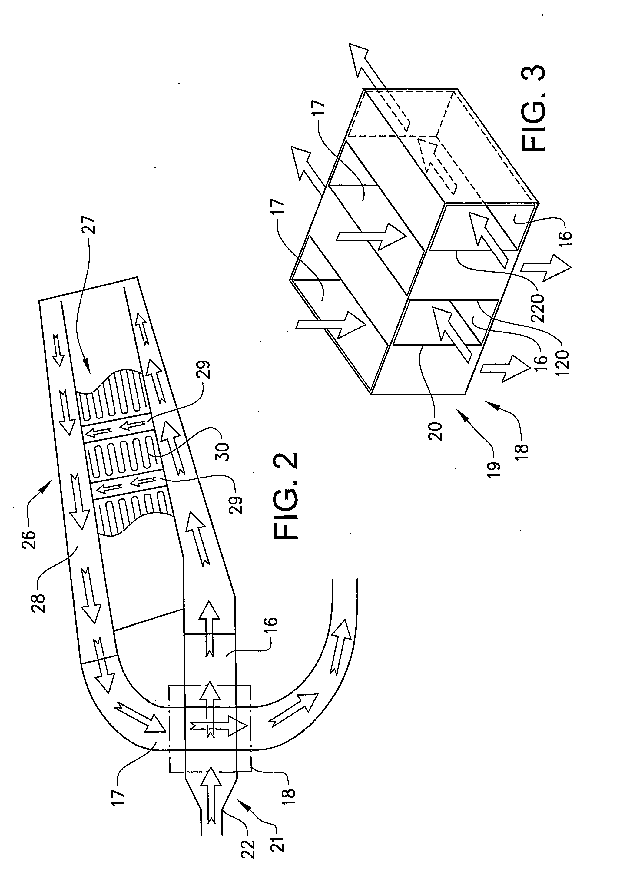
[0009]Due to that the component comprises the plurality of circumferentially spaced second channels, which crosses the plurality of circumferentially spaced first channels, a rigid structure can be achieved.
[0012]Further, by arranging the plurality of circumferentially spaced second channels in a crossing relationship with the plurality of circumferentially spaced first channels, arrangements of sub-systems may be facilitated. For example, the radially spaced channels creates conditions for radially extending elements, such as power take off shafts, oil conduits etc.

Problems solved by technology

In other words, a flow speed increase, which would otherwise be necessitated, is limited.

Method used


Image

  • Annular gas turbine housing component and a gas turbine comprising the component
  • Annular gas turbine housing component and a gas turbine comprising the component
  • Annular gas turbine housing component and a gas turbine comprising the component

Examples


Embodiment Construction

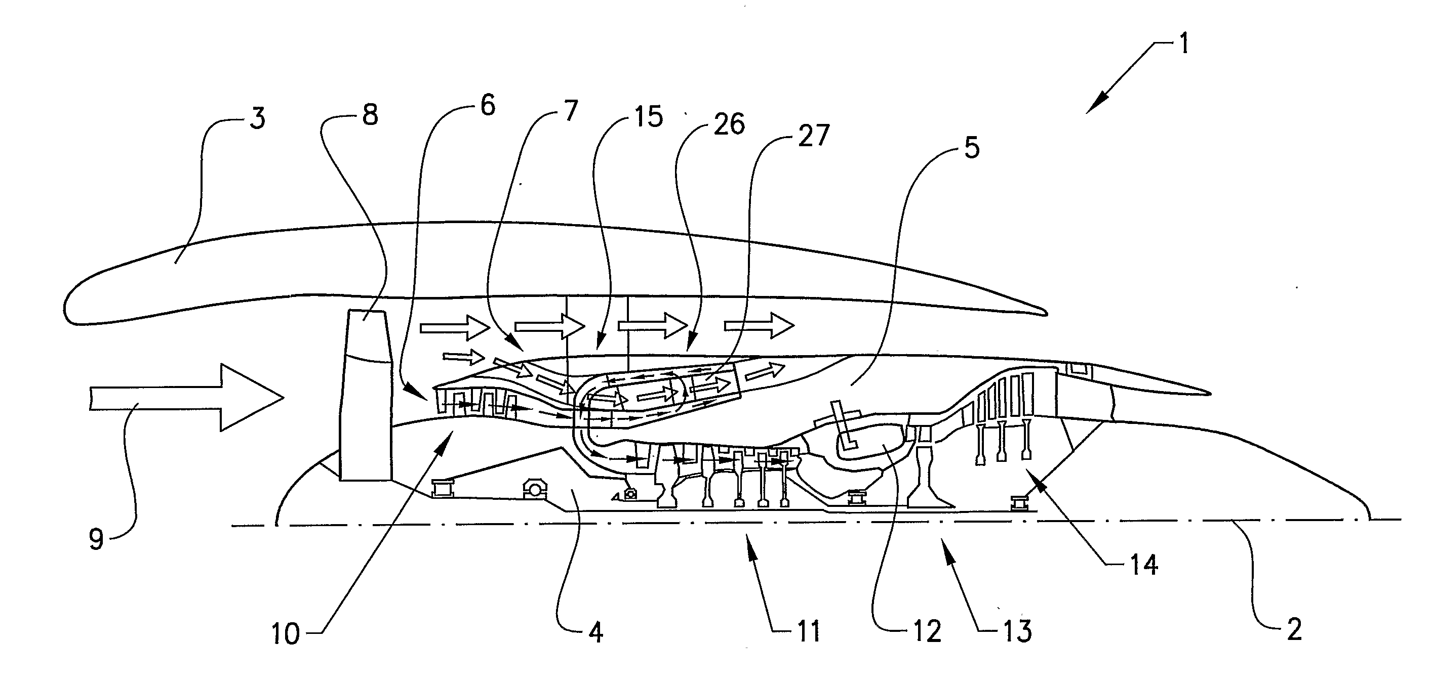
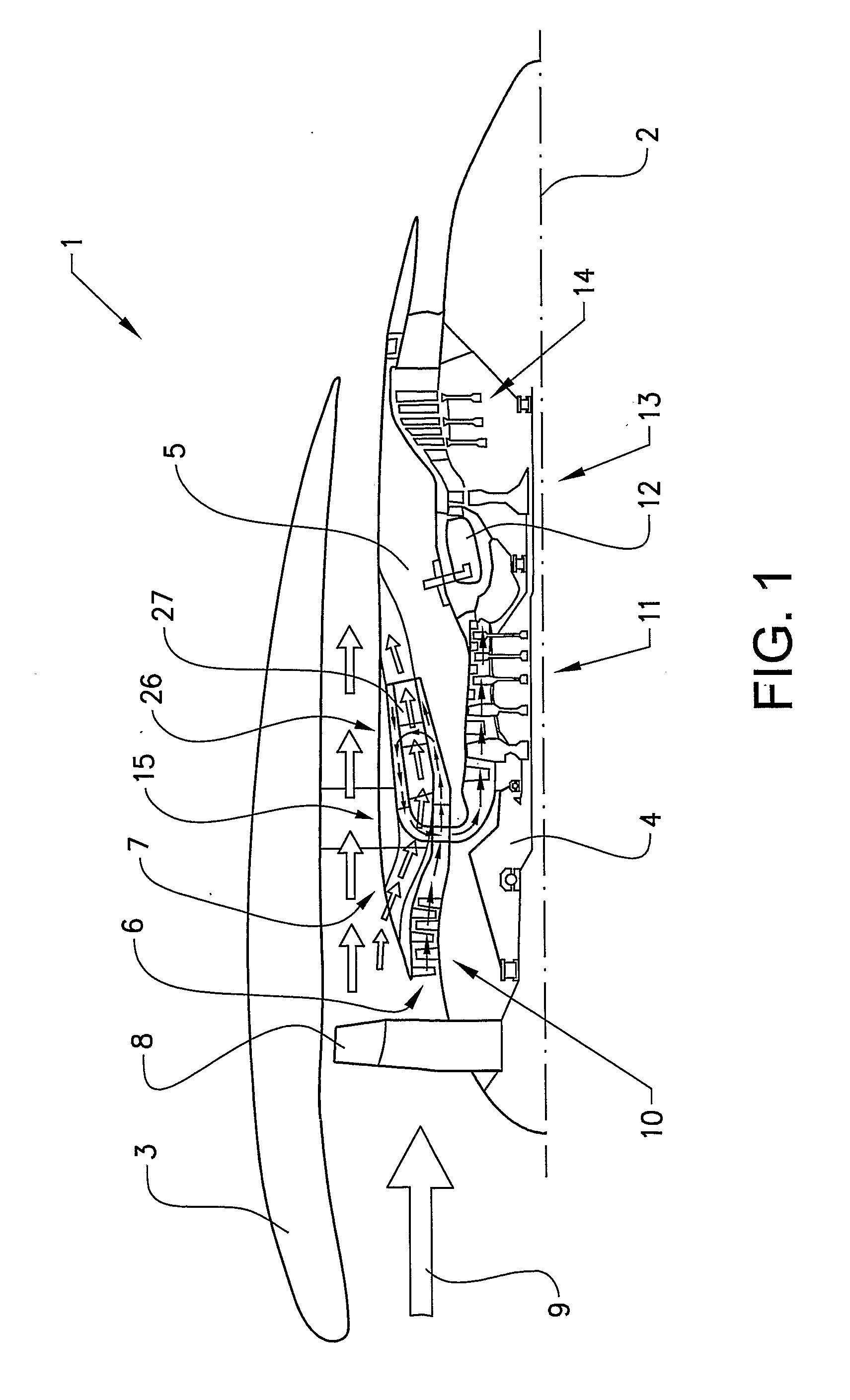
[0024]The invention will below be described for a turbofan gas turbine aircraft engine 1, which in FIG. 1 is circumscribed about an engine longitudinal central axis 2. The engine 1 comprises an outer casing or nacelle 3, an inner casing 4 (rotor) and an intermediate casing 5 which is concentric to the first two casings and divides the gap between them into an inner primary gas channel 6 for the compression of air and a secondary channel 7 in which the engine bypass air flows. The casings are in turn made up of a plurality of components in the axial direction of the engine. Thus, each of the gas channels 6,7 is annular in a cross section perpendicular to the engine longitudinal central axis 2.

[0025]The engine 1 comprises a fan 8 which receives ambient air 9, a booster or low pressure compressor (LPC) 10 and a high pressure compressor (HPC) 11 arranged in the primary gas channel 6, a combustor 12 which mixes fuel with the air pressurized by the high pressure compressor 11 for generati...


PUM


Abstract

The invention relates to an annular gas turbine housing component (15) comprising a plurality of circumferentially spaced first channels (16) for conveying a first gas flow in a first direction and a plurality of circumferentially spaced second channels (17) for conveying a second gas flow in a second direction across the first direction in a crossing position (18) of the first and second channels.

Description

BACKGROUND AND SUMMARY[0001]The present invention relates to an annular gas turbine housing component. The invention is further directed to a gas turbine engine, and especially to an aircraft engine, comprising the component. Thus, the invention is especially, directed to a jet engine.[0002]Jet engine is meant to include various types of engines, which admit air at relatively low velocity, heat it by combustion and shoot it out at a much higher velocity. Accommodated within the term jet engine are, for example, turbojet engines and turbofan engines. The invention will below be described for a turbofan engine, but may of course also be used for other engine types.[0003]An aircraft gas turbine engine of the turbofan type generally comprises a forward fan and booster compressor, a middle core engine, and an aft low pressure power turbine. The core engine comprises a high pressure compressor, a combustor and a high pressure turbine in a serial relationship. The high pressure compressor ...

Claims


Application Information

Patent Timeline
IPC IPC(8): F01D25/24F01D25/08
CPCF01D25/14Y02T50/675F02C7/143Y02T50/60
Inventor JACOBSSON, DENNIS
Owner VOLVO AERO CORP
Learn More