Plasma processing apparatus

Active Publication Date: 2012-06-14
HITACHI HIGH-TECH CORP
View PDF15 Cites 29 Cited by
  • Summary
  • Abstract
  • Description
  • Claims
  • Application Information

AI Technical Summary

Benefits of technology

[0005]According to the present invention, it becomes possible to control the radio-frequency vol

Problems solved by technology

Then, this change in the coupling gives rise to a problem of the occurrence of time-elapsed changes in such factors as etching rate, its uniformity, verticality of the etching profile, and adherence situation of the reaction products onto the etching side wall.
The applicatio

Method used


Image

  • Plasma processing apparatus
  • Plasma processing apparatus
  • Plasma processing apparatus

Examples


Embodiment Construction

[0013]Hereinafter, referring to the drawings, the explanation will be given below concerning embodiments of the present invention.

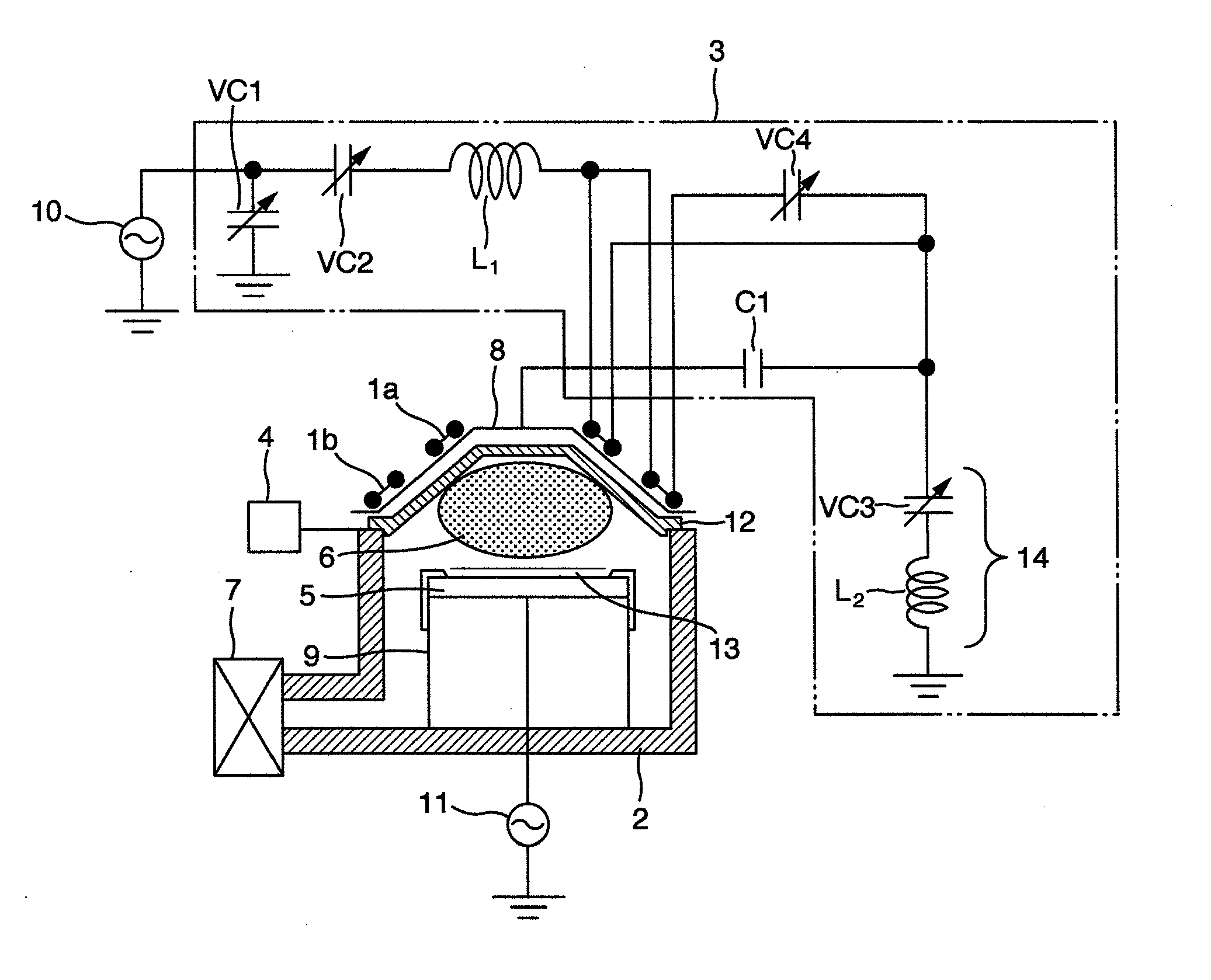
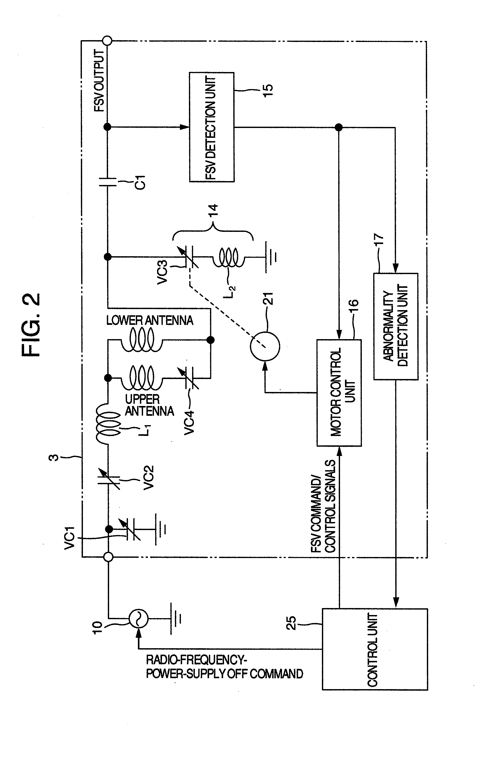
[0014]FIG. 1 is a cross-sectional diagram for illustrating an inductively-coupled plasma etching apparatus where the present invention is used. A cylindrical vacuum processing chamber 2 is equipped with a conical window 12 made of an insulating material, which encloses the upper portion of the vacuum processing chamber 2. A sample stage 5 for mounting a sample 13 thereon is deployed inside the vacuum processing chamber 2. A plasma 6 is generated inside the vacuum processing chamber 2, thereby making it possible to apply the plasma processing to the sample 13. Also, the sample stage 5 is formed on a sample-holding unit 9 including the sample stage 5. A process gas is supplied into the vacuum processing chamber 2 from a gas-supplying device 4. The process gas supplied into the vacuum processing chamber 2 is decompressed and exhausted to maintain a predeterm...


PUM

PropertyMeasurementUnit
Electric potential / voltageaaaaaaaaaa
Inductive effectaaaaaaaaaa

Abstract

In the present invention, there is provided a plasma processing apparatus including a vacuum processing chamber for applying a plasma processing to a sample, a sample stage deployed inside the vacuum processing chamber for mounting the sample thereon, induction antennas provided outside the vacuum processing chamber, a radio-frequency power supply for supplying a radio-frequency power to the induction antennas, and a Faraday shield which is capacitively coupled with the plasma, a radio-frequency voltage being applied to the Faraday shield from the radio-frequency power supply via a matching box, wherein the matching box includes a series LC circuit including a variable capacitor and an inductor, a motor control unit for controlling a motor for the variable capacitor, and a radio-frequency voltage detection unit for detecting the radio-frequency voltage applied to the Faraday shield, the matching box executing a feedback control over the radio-frequency voltage applied to the Faraday shield.

Description

BACKGROUND OF THE INVENTION[0001]The present invention relates to a plasma processing apparatus. More particularly, it relates to a plasma processing apparatus which is preferable for performing a surface processing of a sample such as semiconductor element with the use of the plasma.[0002]As one of the conventional plasma processing apparatuses, there exists an inductively-coupled plasma processing apparatus. In this inductively-coupled plasma processing apparatus, a radio-frequency power supply is connected to coil-shaped induction antennas which are provided along the outside of a vacuum chamber and the radio-frequency power is supplied to the induction antennas to generate the plasma. In the plasma processing apparatus which uses induction antennas like this, the coupling between the induction antennas and the plasma generated inside the vacuum chamber changes by reaction products which adhere to the inside of the processing chamber. Then, this change in the coupling gives rise ...

Claims


Application Information

Patent Timeline
IPC IPC(8): C23F1/08
CPCH01J37/321H01J37/32651H01J37/32183H01J37/32174
Inventor GUSHIKEN, MASAHARUSAITOU, MEGUMUNISHIO, RYOJI
Owner HITACHI HIGH-TECH CORP
Why Eureka
Try Eureka