Vertical cavity surface emitting laser device with angular-selective feedback

a laser device and vertical cavity technology, applied in semiconductor lasers, laser optical resonator construction, laser details, etc., can solve the problems of ring profiles that cannot be realized with a significant power loss, shift of the far field with changing current or temperature, and unwanted artifacts, etc., to achieve large angles, affect the effect of filamentation more easily, and high stabilization

Active Publication Date: 2012-06-14
TRUMPF PHOTONIC COMPONENTS GMBH
View PDF6 Cites 111 Cited by
  • Summary
  • Abstract
  • Description
  • Claims
  • Application Information

AI Technical Summary

Benefits of technology

[0014]With the proposed method it is possible to achieve a higher stabilization for laser radiation emitted at an angle >0 to the optical axis than for a fundamental mode of the laser radiation emitted on the optical axis, if such an on-axis mode would be stabilized by corresponding optical feedback. The on-axis emission can be affected by filamentation more easily, while the large angles are more robust against small inhomogenities of the gain medium or the inner cavity. Higher stabilization in particular means a larger operating range of the laser with respect to driving current and temperature.
[0015]In an advantageous embodiment the thus stabilized intensity distribution is transformed with a further optics to a Gauss like distribution in order to achieve such an intensity distribution in the far field with high stability. To this end, an optics with at least two free form surfaces is required, for example to transform a ring shaped stabilized optical intensity distribution to a Gauss like intensity distribution. With such a measure, a very high stability of a Gauss like intensity distribution can be achieved for large area VCSELs, which is not possible when trying to stabilize the on axis radiation by optical feedback.

Problems solved by technology

Furthermore, due to the coherence of the laser beam unwanted artifacts can appear.
In addition, ring profiles can only be realized with a significant power loss by the beam homogenizers.
This dependence however results in a shift of the far field with changing current or temperature, as the detuning will change.

Method used


Image

  • Vertical cavity surface emitting laser device with angular-selective feedback
  • Vertical cavity surface emitting laser device with angular-selective feedback
  • Vertical cavity surface emitting laser device with angular-selective feedback

Examples


Embodiment Construction

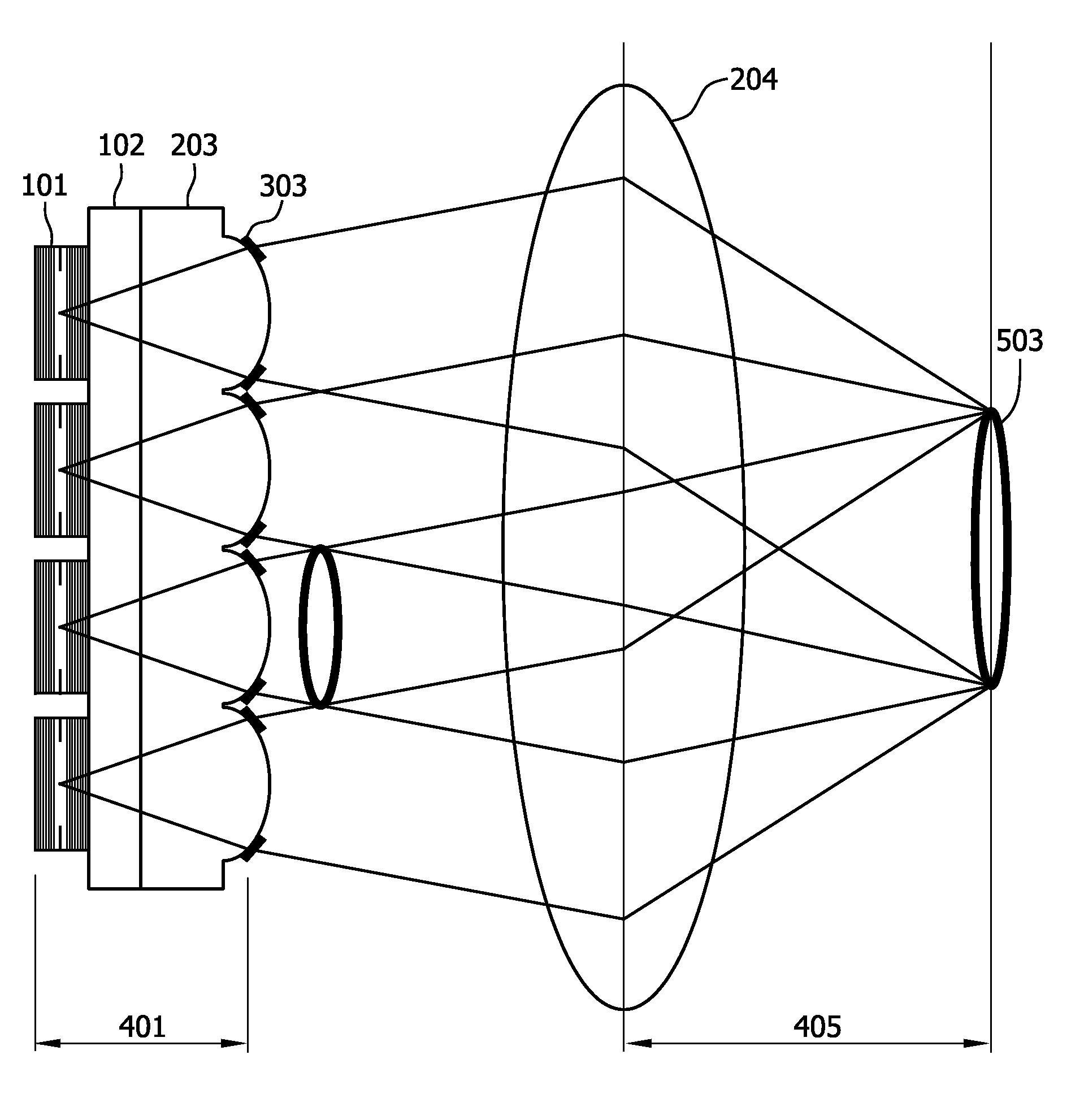
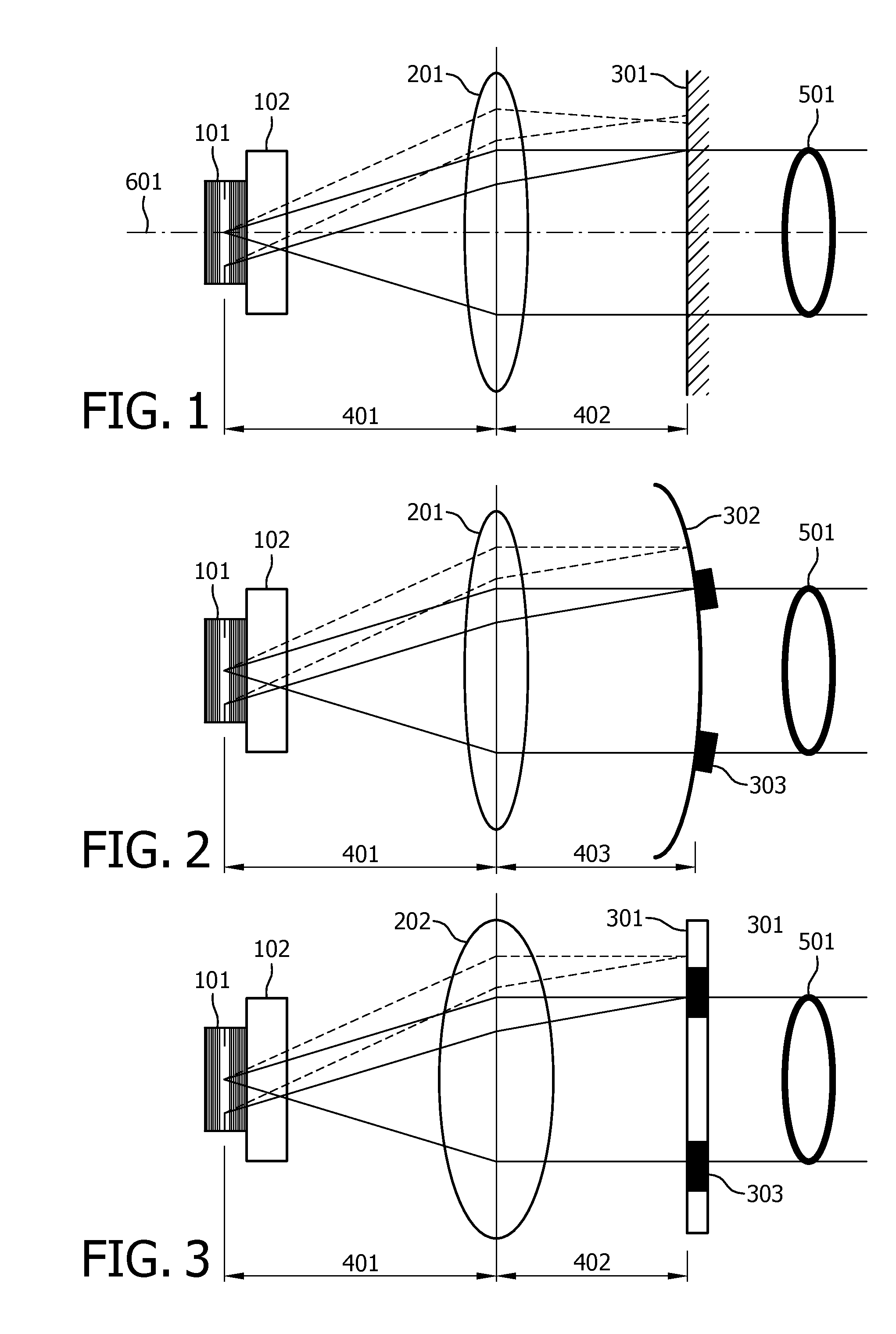
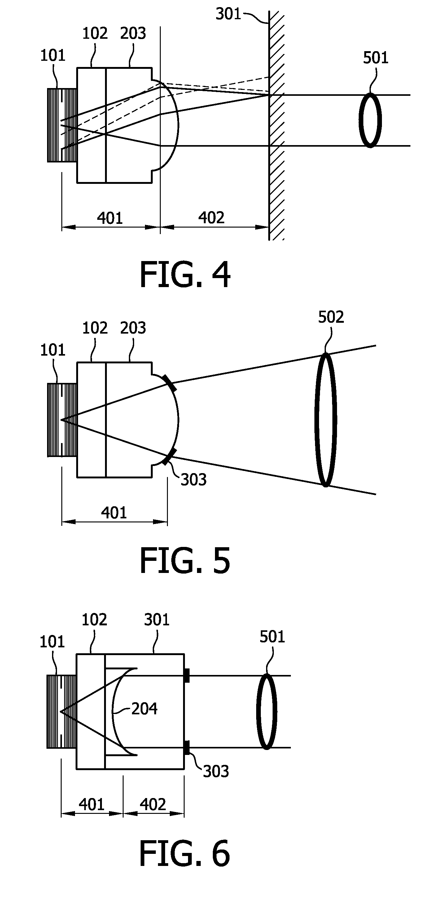
[0030]FIG. 1 shows a first example of the proposed laser device. The laser device comprises a large area VCSEL 101 on an optically transparent substrate 102. The feedback element is formed of a combination of a bi-convex spheric lens 201 and a flat mirror 301 which is partially transparent for the laser radiation. In this example, the bi-convex lens has a focal length of f=25 mm and a diameter of 22.4 mm. The flat mirror 301 has a reflectivity of R=50%. Lens 201 and flat mirror 301 are arranged forming an external cavity in a nearly mirrored self-imaging configuration, i.e. the optical distance 401 between the active layer of the laser and the lens and the optical distance 402 between the lens and the mirror are approximately equal to the focal length f of the lens.

[0031]Due to the spheric aberration of lens 201, only light emitted under the right angle to the optical axis 601 is perfectly collimated. After reflection from the external mirror 301 it is fed back into the active area ...


PUM


Abstract

The present invention relates to a laser device comprising at least one large area VCSEL (101) and at least one optical feedback element (201, 301) providing an angular-selective feedback for laser radiation emitted from the laser. The angular-selective feedback is higher for at least one portion of laser radiation emitted at angles θ>0 to the optical axis (601) of the laser than for laser radiation emitted on said optical axis (601). The invention also refers to a method of stabilizing a laser emission of a large area VCSEL in a desired angular distribution (501, 502). With the proposed device and method, the intensity distribution of a large area VCSEL can be stabilized in a desired shape, for example a ring shape.

Description

TECHNICAL FIELD AND BACKGROUND OF THE INVENTION[0001]The present invention relates to a laser device comprising at least one large area vertical cavity surface emitting laser (VCSEL) and at least one optical feedback element providing an angular-selective feedback for laser radiation emitted from said laser. The invention also refers to a method of stabilizing the laser emission of a large area vertical cavity surface emitting laser by angular-selective optical feedback.[0002]High power diode lasers show an increasing number of applications in material processing like cutting, welding or soldering as well as in medicine. Also vertical cavity surface emitting lasers now reach higher output power per device and offer easy scalability in form of 2-dimensional arrays.[0003]The emission of lasers is usually described in terms of Gaussian modes and most lasers are designed to have a fundamental Gaussian intensity distribution. For many laser applications however, especially in material pr...

Claims


Application Information

Patent Timeline
Patent Type & Authority Applications(United States)
IPC IPC(8): H01S5/068H01S5/183
CPCH01S5/14H01S5/18388H01S2301/203H01S5/187H01S2301/18H01S5/18394H01S3/08068H01S5/0287H01S5/1021H01S5/141H01S5/11
Inventor MOENCH, HOLGERGRONENBORN, STEPHAN
Owner TRUMPF PHOTONIC COMPONENTS GMBH
Why Eureka
Try Eureka