Electrostatic Loudspeaker System
- Summary
- Abstract
- Description
- Claims
- Application Information
AI Technical Summary
Benefits of technology
Problems solved by technology
Method used
Image

Examples
Embodiment Construction
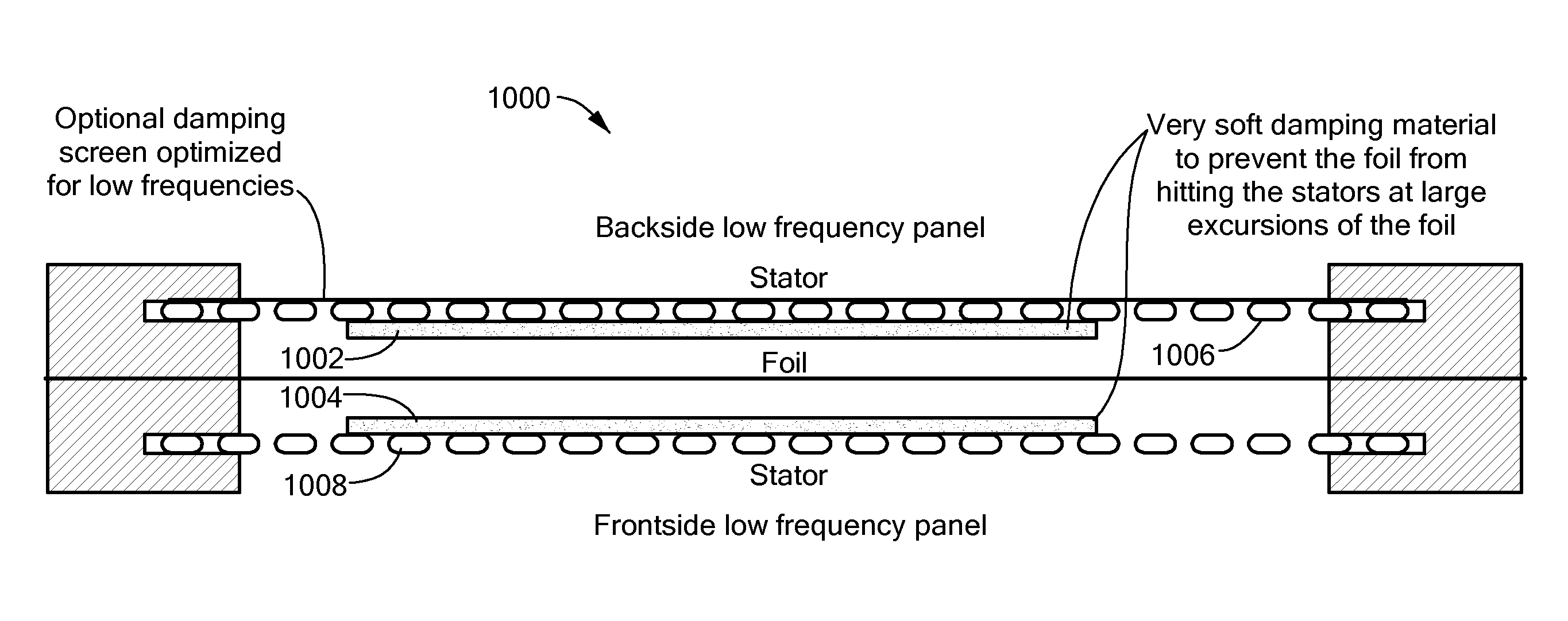
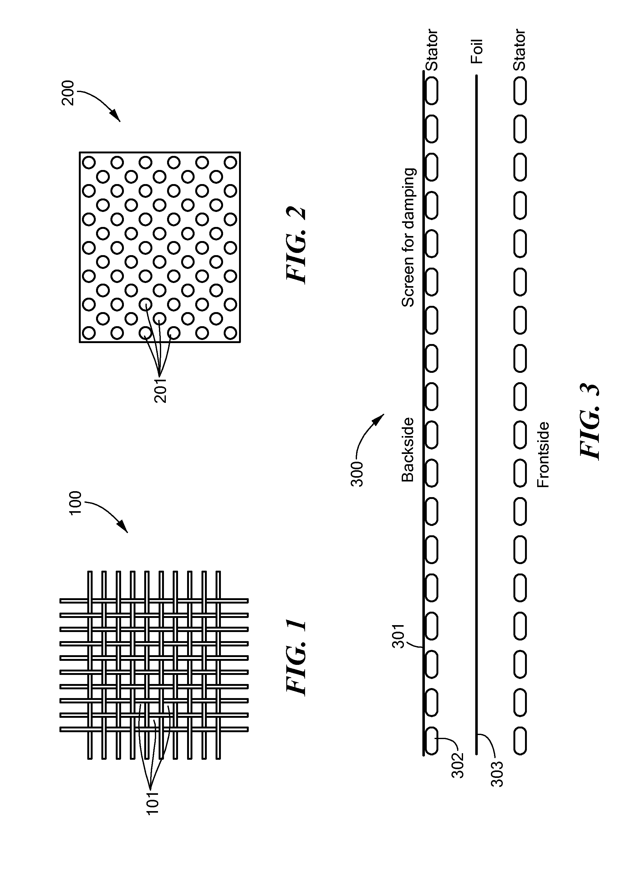
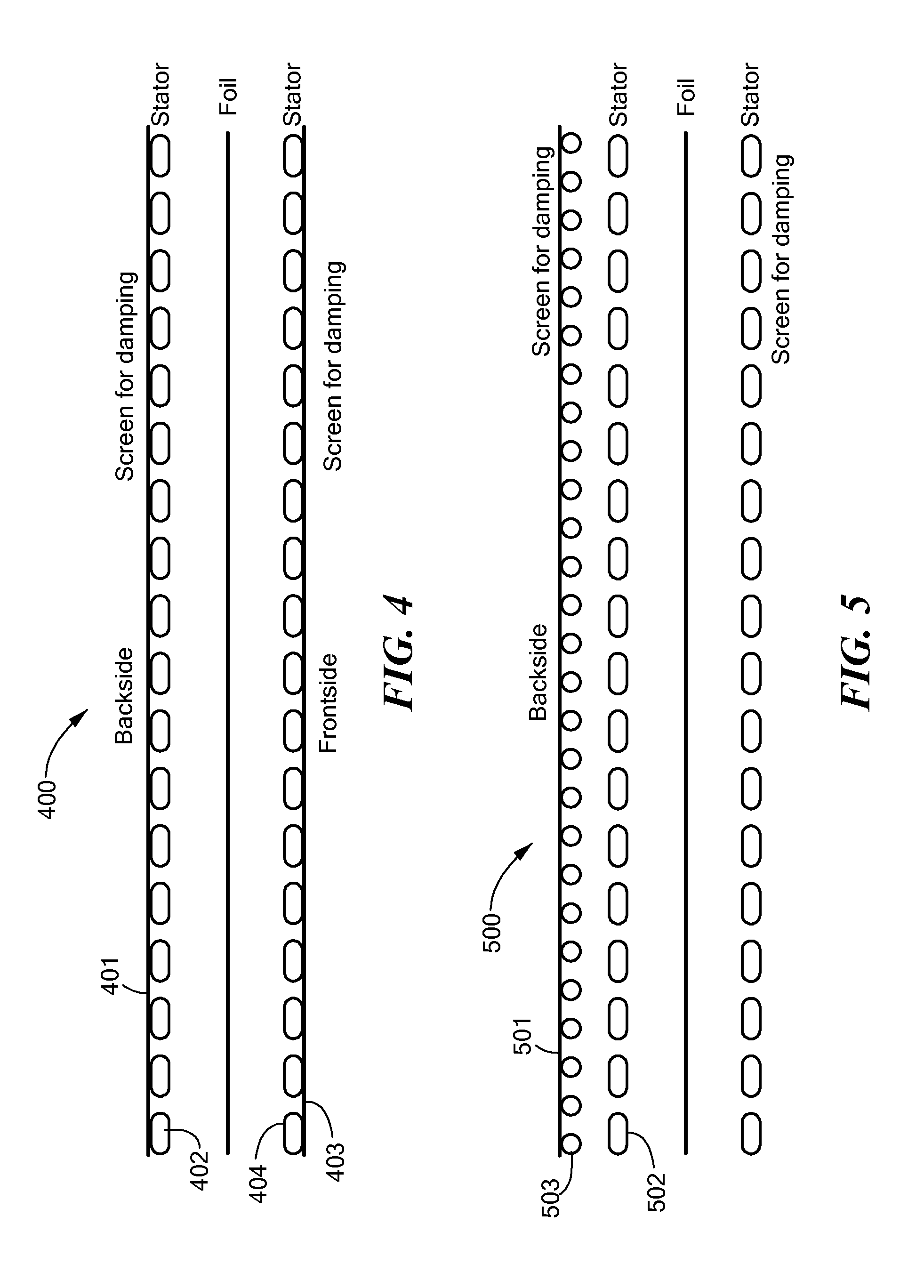
[0022]An embodiment of the present invention provides an improved electrostatic speaker of the type having a pair of stators and a diaphragm disposed between the stators. The speaker renders, into an acoustic output, an electrical audio input coupled to the speaker. The improvement includes a damping screen placed adjacent an outside surface of least one of the stators. The improved speaker is configured so that the damping screen reduces distortion of the acoustic output rendered by the diaphragm. The distortion includes effects of resonance of the diaphragm.
[0023]The damping screen may include a fabric selected to provide effective damping of resonance of the diaphragm at a fundamental frequency. Optionally or alternatively, the improved speaker may include a damping tape placed on a central portion of the damping screen. The damping tape provides further damping of the diaphragm. In some embodiments, the area of the damping tape may be about 15% of the area of the diaphragm. In s...
PUM
 Abstract
Description
Claims
Application Information
 - Generate Ideas
- Intellectual Property
- Life Sciences
- Materials
- Tech Scout
- Unparalleled Data Quality
- Higher Quality Content
- 60% Fewer Hallucinations
Browse by: Latest US Patents, China's latest patents, Technical Efficacy Thesaurus, Application Domain, Technology Topic, Popular Technical Reports.
© 2025 PatSnap. All rights reserved.Legal|Privacy policy|Modern Slavery Act Transparency Statement|Sitemap|About US| Contact US: help@patsnap.com