Deposition of thermoelectric materials by printing

a thermoelectric material and printing technology, applied in the direction of duplicating/marking methods, mechanical vibration separation, coatings, etc., can solve the problems of large mechanical stresses in the thermoelectric layer produced, heavy technology implementation, and inability to form thin films, etc., to achieve good mechanical properties and high thermoelectric performance

Inactive Publication Date: 2012-06-14
COMMISSARIAT A LENERGIE ATOMIQUE ET AUX ENERGIES ALTERNATIVES
View PDF4 Cites 11 Cited by
  • Summary
  • Abstract
  • Description
  • Claims
  • Application Information

AI Technical Summary

Benefits of technology

[0015]A need exists to provide a method for producing a layer of thermoelectric material having both good mechanical properties and high thermoelectric performances.

Problems solved by technology

Thin-film deposition methods, like PVD or CVD technology, are inappropriate for forming layers with a thickness of more than 50 μm.
This technology, which is heavy to implement, then becomes difficult to apply on a large scale.
Large mechanical stresses are however observed in the thermoelectric layer produced by this technique.

Method used


Image

  • Deposition of thermoelectric materials by printing
  • Deposition of thermoelectric materials by printing
  • Deposition of thermoelectric materials by printing

Examples


Embodiment Construction

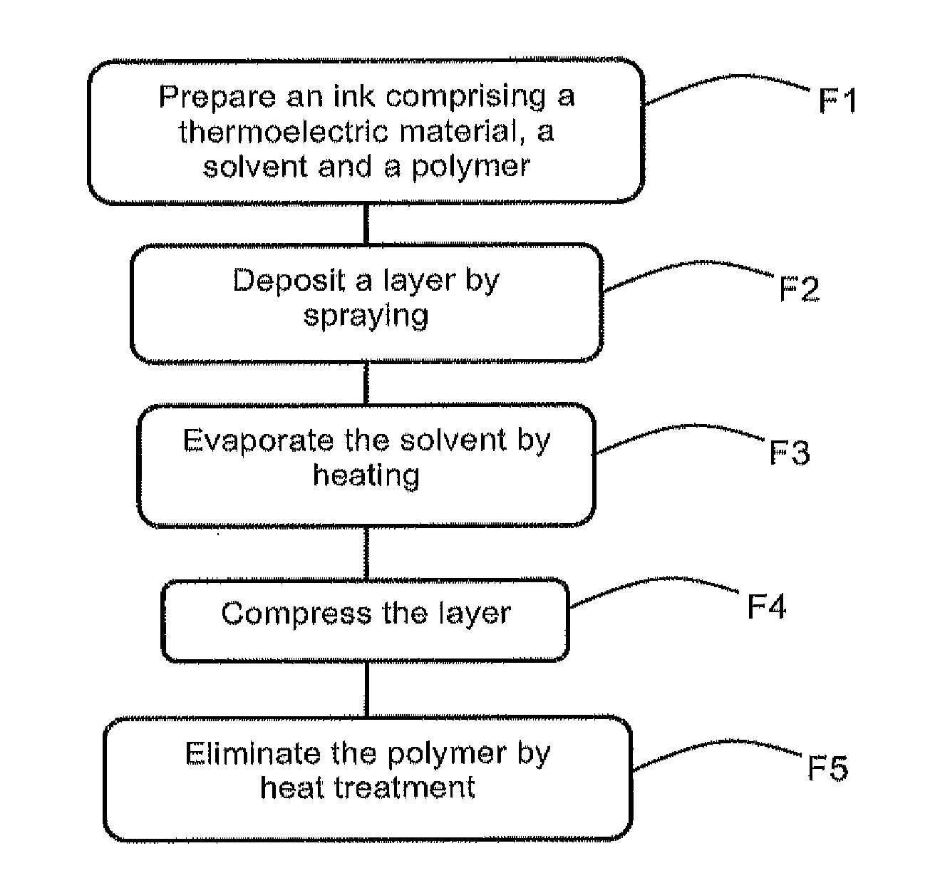
[0021]It is proposed here to limit the internal stresses due to elimination of the solvent and of the polymer material by depositing the ink by spraying. The spraying conditions are chosen such that a part of the solvent is evaporated when deposition is performed. A porous layer is then obtained, which will enable the stresses to be relaxed when final elimination of the additives takes place.

[0022]FIG. 2 represents steps of a method for producing layers of thermoelectric material with relaxed stresses, in flowchart form.

[0023]In a step F1, an ink compatible with the spray printing technique is prepared. The ink comprises a thermoelectric material designed to form the thermoelements, a polymer material and a solvent.

[0024]The thermoelectric material is preferably in the form of semi-metallic or semi-conducting particles with a diameter comprised between 10 nm and 10 μm, dispersed in the solvent. The thermoelectric material can be chosen from bismuth and tellurium alloys, for example ...


PUM

PropertyMeasurementUnit
thicknessaaaaaaaaaa
thicknessaaaaaaaaaa
diameteraaaaaaaaaa

Abstract

A method for producing a layer of thermoelectric material with a thickness comprised between 50 μm and 500 μm on a substrate comprises preparing an ink comprising the thermoelectric material, a solvent and a binding polymer material, depositing a layer of ink on a substrate, heating the layer of ink to evaporate the solvent, compressing the layer and performing heat treatment to eliminate the binding polymer material. Deposition of the layer of ink is performed by pressurized spraying under conditions such that the solvent is partially evaporated before reaching the substrate.

Description

BACKGROUND OF THE INVENTION[0001]The invention relates to the production of thermoelectric modules, and more particularly to deposition of layers of thermoelectric material by printing.STATE OF THE ART[0002]A thermoelectric module comprises several thermoelectric elements, also called thermoelements, electrically connected in series and thermally connected in parallel. The performances of such a module depend on the thermoelectric materials used and on the geometry of the module.[0003]Thermoelectric materials having a high figure of merit ZT at the operating temperature of the module are generally chosen. The figure of merit is written:ZT=σ·S2λT,[0004]where σ is the electrical conductivity, S is the Seebeck coefficient, λ the thermal conductivity and T the temperature. The product σ·S2 is called power factor.[0005]A material with good thermoelectric properties therefore presents high electrical conductivity and Seebeck coefficient and a low thermal conductivity. At ambient temperatu...

Claims


Application Information

Patent Timeline
Patent Type & Authority Applications(United States)
IPC IPC(8): B05D5/12B06B1/20
CPCB41M5/0011B41M7/00H01L35/34H01L35/16B41M7/009H10N10/852H10N10/01
Inventor NAVONE, CHRISTELLESOULIER, MATHIEU
Owner COMMISSARIAT A LENERGIE ATOMIQUE ET AUX ENERGIES ALTERNATIVES
Why Eureka
Try Eureka