Method for placing spinal implants

a technology for spinal implants and implants, applied in the field of spinal implants, can solve the problems of patient paralysis or even death, surgeon's inability to accurately align the pedicle screw, etc., and achieve the effect of avoiding unintended impingement of the devi

Inactive Publication Date: 2012-06-14
MANNION RICHARD
View PDF10 Cites 115 Cited by
  • Summary
  • Abstract
  • Description
  • Claims
  • Application Information

AI Technical Summary

Benefits of technology

[0019]“An optimal” as used in the claim phrase “to thereby substantially demarcate an optimal alignment, trajectory and angulation for the spinal implant device” means one of the several such spinal implant device locations which a surgeon may deem “optimal” to provide 3-point fixation of the device relative to the patient's relevant anatomical, vertebral landmarks, while avoiding unintended impingement of the device on adjacent spinal, vascular or neurological elements.

Problems solved by technology

However, current methods of spinal fusion carry a risk of vascular, visceral and neurological injury caused by inaccurate placement of pedicle screws, or inappropriately-sized instrumentation, which may lead to patient paralysis or even fatality.
A primary cause of misplacement is the surgeon's inability to accurately align the pedicle screw and provide it with an appropriate trajectory given the particular spinal geometry involved.
Misaligned pedicle screw problems range from minor issues to more serious problems such as a lack of spinal integrity and resulting paralysis or other serious health issues.

Method used


Image

  • Method for placing spinal implants
  • Method for placing spinal implants
  • Method for placing spinal implants

Examples


Embodiment Construction

[0030]Set forth below is a description of what are believed to be the preferred embodiments and / or best examples of the invention claimed. Future and present alternatives and modifications to this preferred embodiment are contemplated. Any alternatives or modifications which make insubstantial changes in function, in purpose, in structure, or in result are intended to be covered by the claims of this patent.

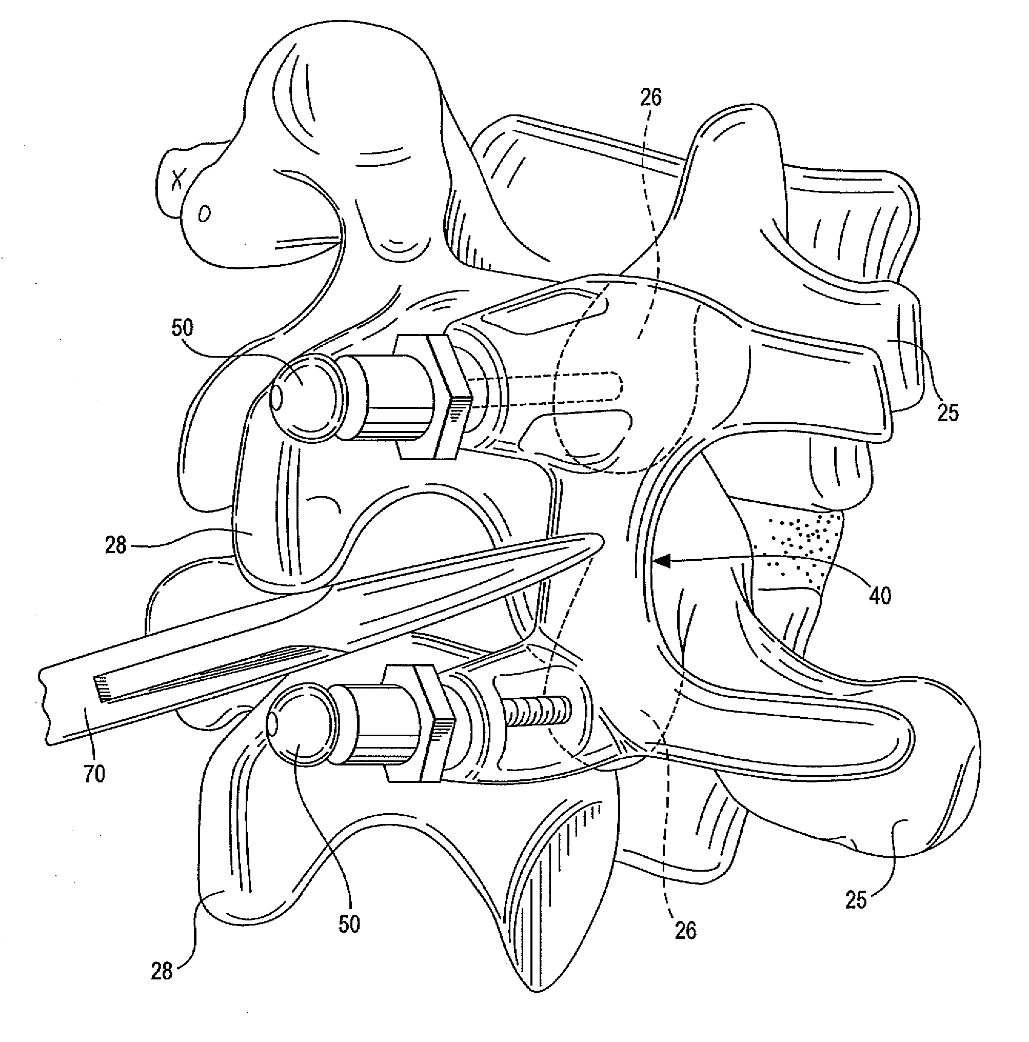
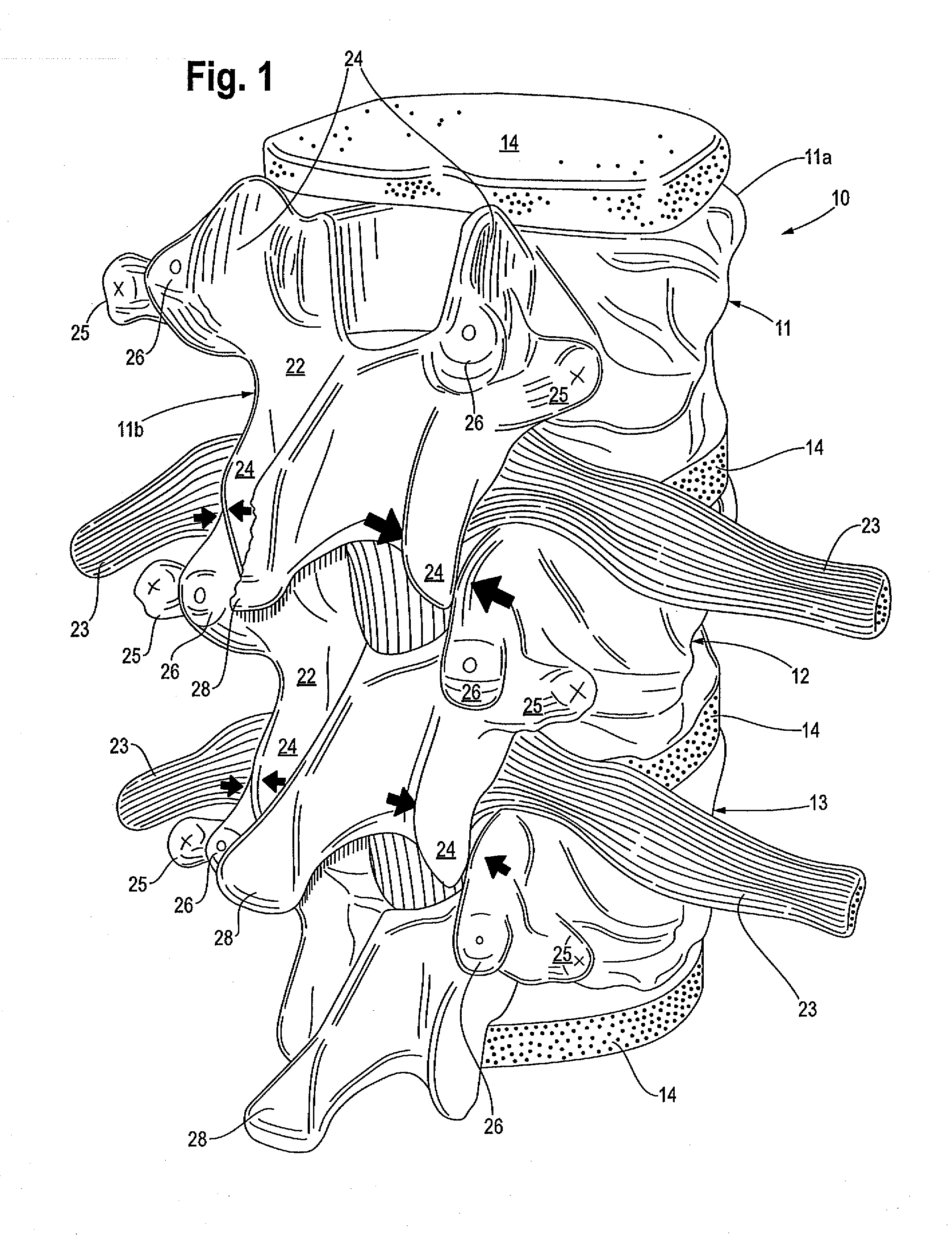
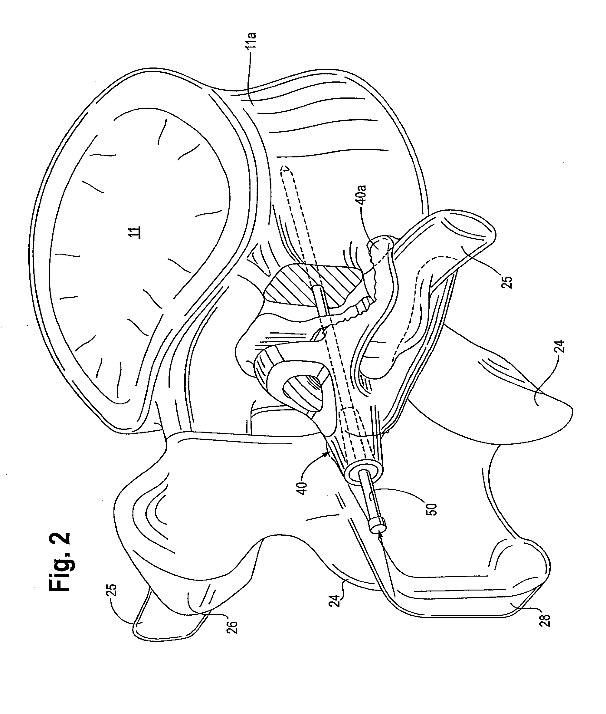
[0031]Referring first to FIG. 1, a portion of the human spine in the lumbar region is generally designated by reference numeral 10. Spinal region 10 includes individual vertebrae 11, 12 and 13, each separated by cartilage and muscle loosely represented by reference numeral 14, and spinal nerves 23. (The spinal cord is attached to the spinal nerves and is not shown in FIG. 1. Spinal canal 30 is shown in FIG. 3.) A typical vertebrae 11 consists of an anterior (front) segment 11a, which is the vertebral body, and a posterio (back) portion 11b, which is the vertebral (neural) arch, w...


PUM


Abstract

A process for utilizing a spinal implant guide made using a diagnostic imaging tool to facilitate implantation of a device in the spine. The spinal implant guide preferably has a body designed to conform to certain predetermined, patient-specific anatomical vertebral landmarks. The guide may be fitted to the anatomical vertebral landmarks pre-operatively and/or during a surgical procedure using 3-point fixation technique to thereby substantially demarcate an optimal alignment, trajectory and angulation for the spinal implant device.

Description

BACKGROUND OF THE INVENTION[0001]The present inventions generally relate to methods for augmenting the structural stability of the spine. More specifically, methods are disclosed and claimed for placing pedicle screws in the spine using synthetic spine models creating using diagnostic imaging tools, and surgical placement techniques that can be replicated.[0002]In human anatomy, the vertebral column (backbone or spine) is a column usually consisting of 24 articulating vertebrae, and multiple fused vertebrae in the sacrum and the coccyx. The 24 articulating vertebrae are grouped under the names cervical (7 vertebrae in the neck), thoracic (12 vertebrae in the chest area) and lumbar (5 vertebrae in the lower back), according to the regions they occupy. The spine is situated in the dorsal aspect of the torso, separated by intervertebral discs. It houses and protects the spinal cord in its spinal canal.[0003]Spinal fusion procedures involving the implantation of pedicle screws have stea...

Claims


Application Information

Patent Timeline
Patent Type & Authority Applications(United States)
IPC IPC(8): A61B17/56
CPCA61B17/1757A61B17/8897A61B2017/90A61B2017/568A61B2017/00526A61B17/90
Inventor MANNION, RICHARD
Owner MANNION RICHARD
Why Eureka
Try Eureka