Skin radiation apparatus and method

Active Publication Date: 2012-06-14
KONINKLIJKE PHILIPS ELECTRONICS NV
View PDF5 Cites 10 Cited by
  • Summary
  • Abstract
  • Description
  • Claims
  • Application Information

AI Technical Summary

Benefits of technology

[0030]In another variant of the last embodiment, the detection unit is arranged to detect a skin condition in a line shaped detection area that is positioned ahead in the second direction with respect to the line shaped radiation area. This is advantageous, as the process of determining the skin condition profile, the process of calculating the power density distribution and the process of generating and applying the line-shaped radiation pattern can take place simultaneously, therewith shortening the total time of the treatment.
[0031]The detection unit may be moved independently from the photon radiation unit. However it is advantageous if the detection unit and the photon radiation unit are jointly moved. This simplifies the mechanical requirements of the apparatus. In an embodiment the detection unit and the photon radiation unit are arranged in a common housing that is moved by the movement facility. Movement may take place stepwise or continuously. In case of a continuous movement the control unit may stepwise change the power density distribution within the line-shaped radiation pattern each time the movement has proceeded over a predetermined distance in the second direction. Alternatively the skin radiation apparatus may have an interpolation unit to calculate an interpolated power density distribution that changes substantially co

Problems solved by technology

These devices do not allow for a specific dose depending on the severity of the plaque itself.
Irradiation of the healthy skin can have negative effects such as ageing or even cancer.
This can however be an arduous task as the patient's skin may have hundreds or even thousands of mutually i

Method used


Image

  • Skin radiation apparatus and method
  • Skin radiation apparatus and method
  • Skin radiation apparatus and method

Examples


first embodiment

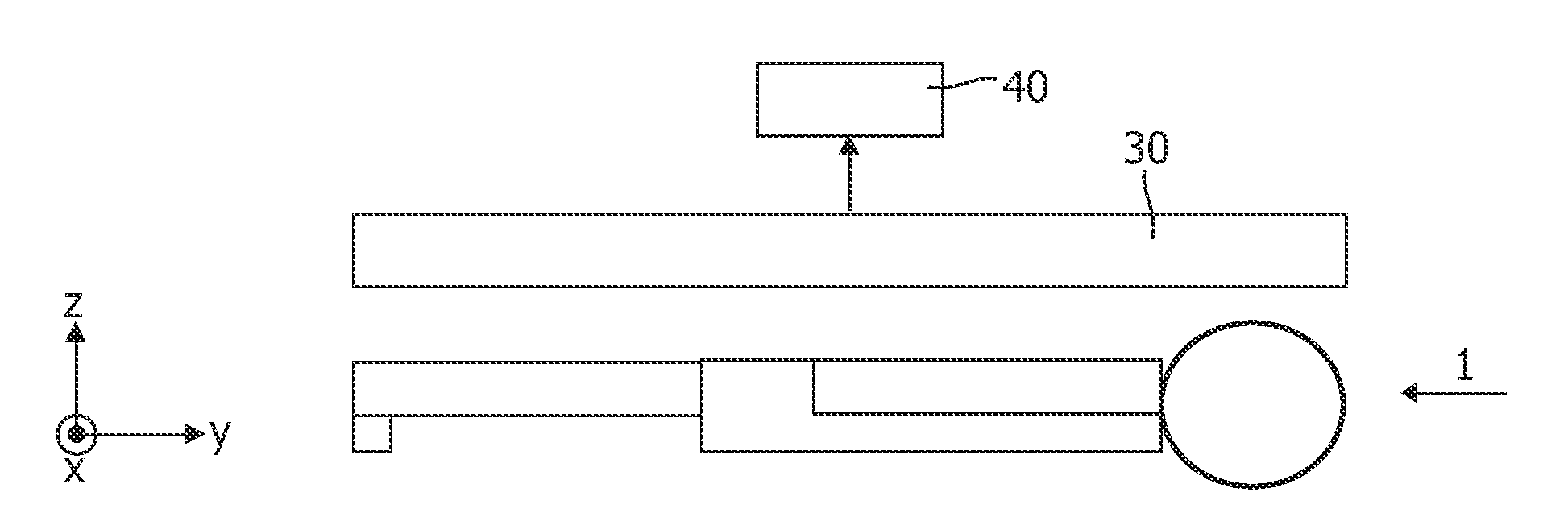
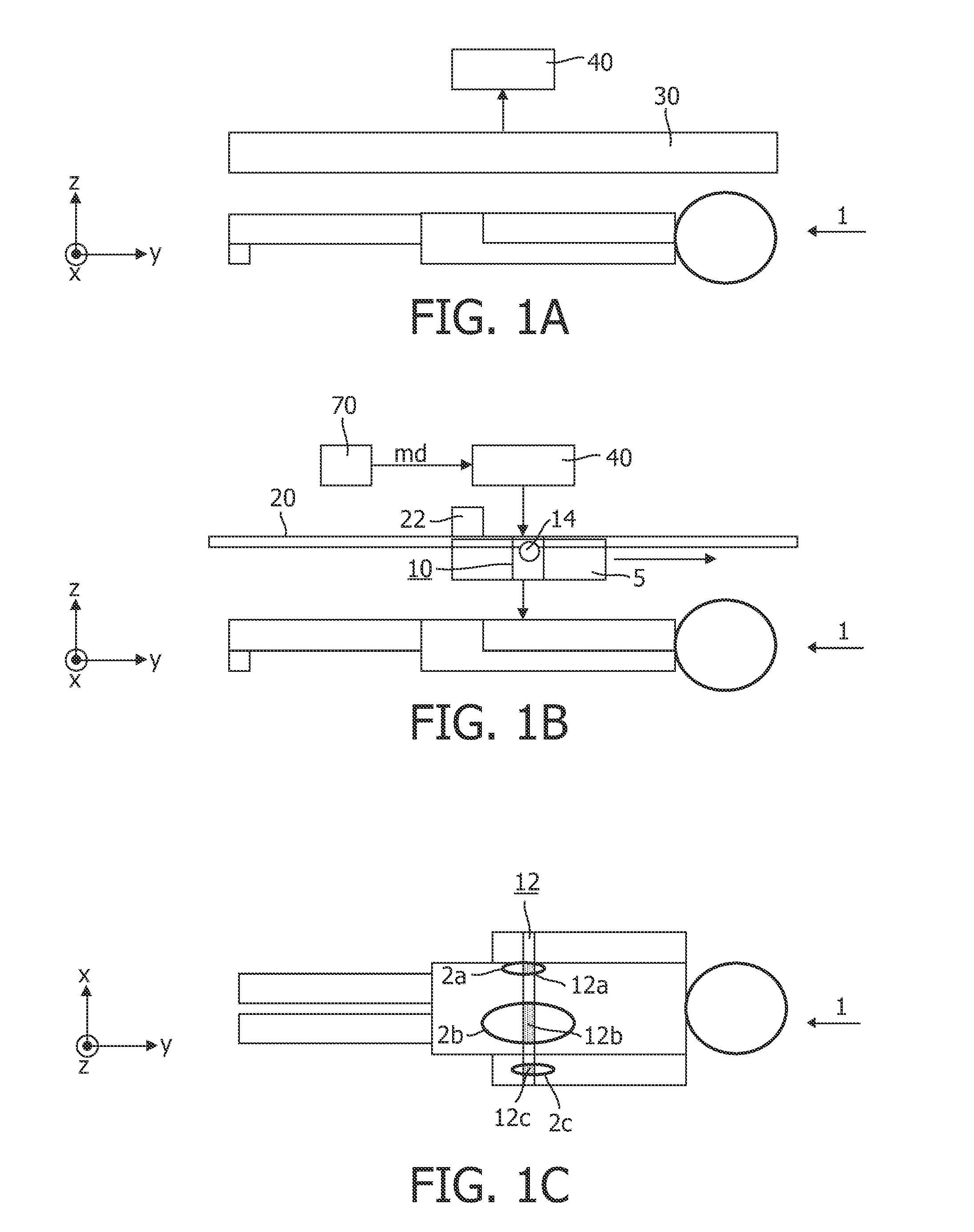
[0064]FIGS. 1A to 1C show a skin radiation apparatus. For clarity each of the FIGS. 1A, 1B show a respective part of the skin radiation apparatus. As shown in FIG. 1B, the apparatus comprises a photon radiation unit 10 for generating a line-shaped radiation pattern 12 extending in a first direction x. The photon radiation unit 10, arranged in a housing 5, comprises a photon radiation source 14. In addition the photon radiation unit 10 may comprise optical elements for controlling a beam radiated by the radiation source 14, such as mirrors, lenses, shutters etc. The apparatus further comprises a movement facility 20 for moving the line shaped radiation pattern in a second direction y transverse to the first direction x. The movement facility comprises for example a pair of rails 20 and an actuator 22. During operation the actuator 22 causes the housing 5 with the photon radiation unit 10 to displace in the y-direction along the pair of rails 22. Therewith also the line shaped radiati...

second embodiment

[0086]FIG. 5B shows a second embodiment, wherein the power of the laser 14 is modulated by a laser driver 144, controlled by the controller 40. The laser beam emitted by the laser 14 is directed towards a rotating hexagonal mirror 146, that reflects the radiation of the laser 14 towards a position within the line shaped area 12 that is to be irradiated.

[0087]In the embodiment of FIG. 5C, the photon radiation source 14 comprises a plurality of radiation source elements 14a, . . . , 14x, such as for example light emitting diodes (LED), that are each capable of radiating a respective portion within the line shape area of the skin. The photon radiation source 14 is controlled by a driver 148 that is on its turn controlled by the controller 40.

[0088]Arithmetical and logical operations carried out by various parts of the apparatus of the control unit 40, by the detection unit 30, and the drivers 140, 144 or 148 may be carried out by dedicated hardware, by software in a programmable proces...


PUM


Abstract

A skin radiation apparatus comprises: —a photon radiation unit (10) for generating a line-shaped radiation pattern (12) extending in a first direction (x), the photon radiation unit comprising a photon radiation source (14), —a movement facility (20, 22) for moving the line shaped radiation pattern in a second direction (y) transverse to the first direction (x), —a detection unit (30) for detecting a skin condition profile, —a control unit (40) for controlling an power density distribution for the line-shaped radiation pattern dependent on the skin condition profile detected by the detection unit (30).

Description

FIELD OF THE INVENTION[0001]The present invention relates to a skin radiation apparatus.[0002]The present invention further relates to a skin radiation method.BACKGROUND OF THE INVENTION[0003]Psoriasis is a chronic, non-infectious inflammatory skin disease characterized by well-demarcated plaques where the cells proliferate quicker than normal (hyperprofileration), leading to a very dry and red skin. The proliferation rate of cells in the epidermis is controlled by the combination of the growth fraction and cell cycle time. In normal skin, the number of cells produced is balanced by the number of cells leaving the epidermal proliferative pool. The time required for a cell to transit between the basal layer and the stratum corneum of the skin (basically from birth to death and getting loose from the skin) is about 4 weeks, while for psoriasis patients, this time is substantially shorter (about 4 days).[0004]Phototherapy has proven an effective treatment of psoriasis. These include br...

Claims


Application Information

Patent Timeline
IPC IPC(8): A61N5/01
CPCA61B18/20A61B2018/00904A61B2018/2085A61N5/01A61N2005/067A61N2005/0637A61N2005/0652A61N2005/0661A61N5/0616A61B2018/20351A61B2018/20355A61B2018/20361A61N5/067
Inventor WAGENAAR CACCIOLA, GIOVANNARITZ, ARNDGIELEN, VINCENT STEFAN DAVIDASHDOWN, IAN EDWARDLOVELAND, DAMIEN
Owner KONINKLIJKE PHILIPS ELECTRONICS NV
Why Eureka
Try Eureka