[0021]It is therefore an object of the present invention to overcome the disadvantages of the prior art and to provide a fault-ride-through control that enables stable fault-ride-through, e.g. in a network
system with a weak connection grid.
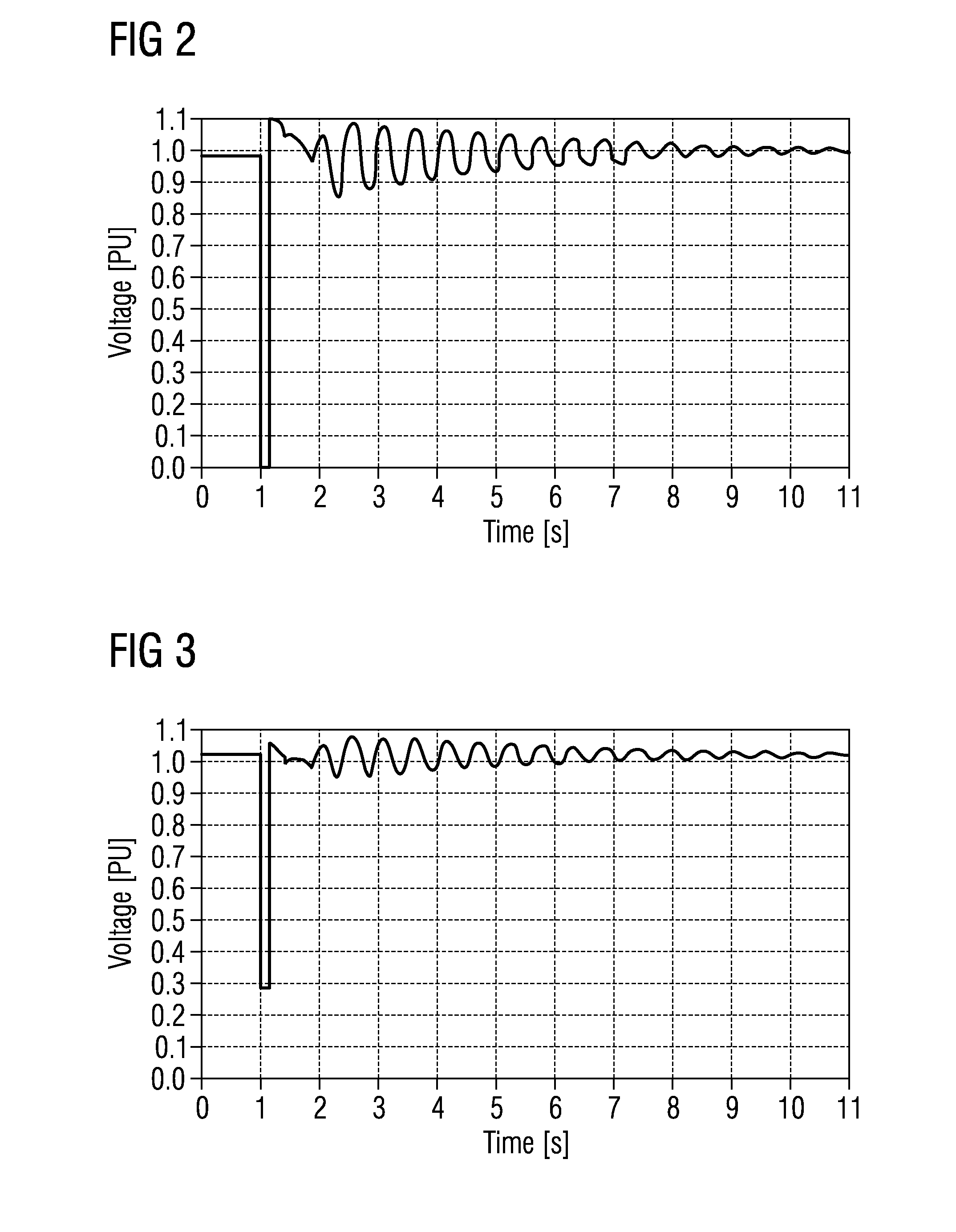
[0027]The inventors of the present invention have recognized that such instabilities can be avoided, if the active current and / or the active power are reduced to a specific value in case a voltage-dip is detected in a power line. The specific value may be a certain, predetermined and / or fixed value. I.e. the active current and / or the active power fed into the power network is reduced to a specific value independent or not necessary only dependent of the voltage-dip value. Thereby, an improved and stable fault ride through performance of each power generating unit and the entire network or
power grid can be achieved. The power generating unit does not have to be disconnected, if a network comprises a weak connection grid for connecting the power generating units, is exposed to severe short circuit faults. Thereby, availability of the entire power network and of each power generating unit is improved.
[0032]The fault-ride-through
recovery method may have a step of waiting until oscillations of the active current and / or active power have faded out after reducing the active current and / or active power due to the voltage-dip. Subsequently the active current and / or active power may be ramped back, i.e. increased to the value prior to the voltage-dip. Particularly, the fault-ride-through
recovery method may comprise a step of waiting until oscillations of the active current and / or active power have been reduced below a pre-determined threshold. Since the active recovery current and / or active power are only increased from a specific value after the fault is cleared and the generator voltage has recovered to a pre-determined threshold, the stability of the generators and entire power network can be ensured. The ramp up may be performed by a specific, particularly pre-determined function, e.g. by a linear function.
[0033]This fault-ride-through
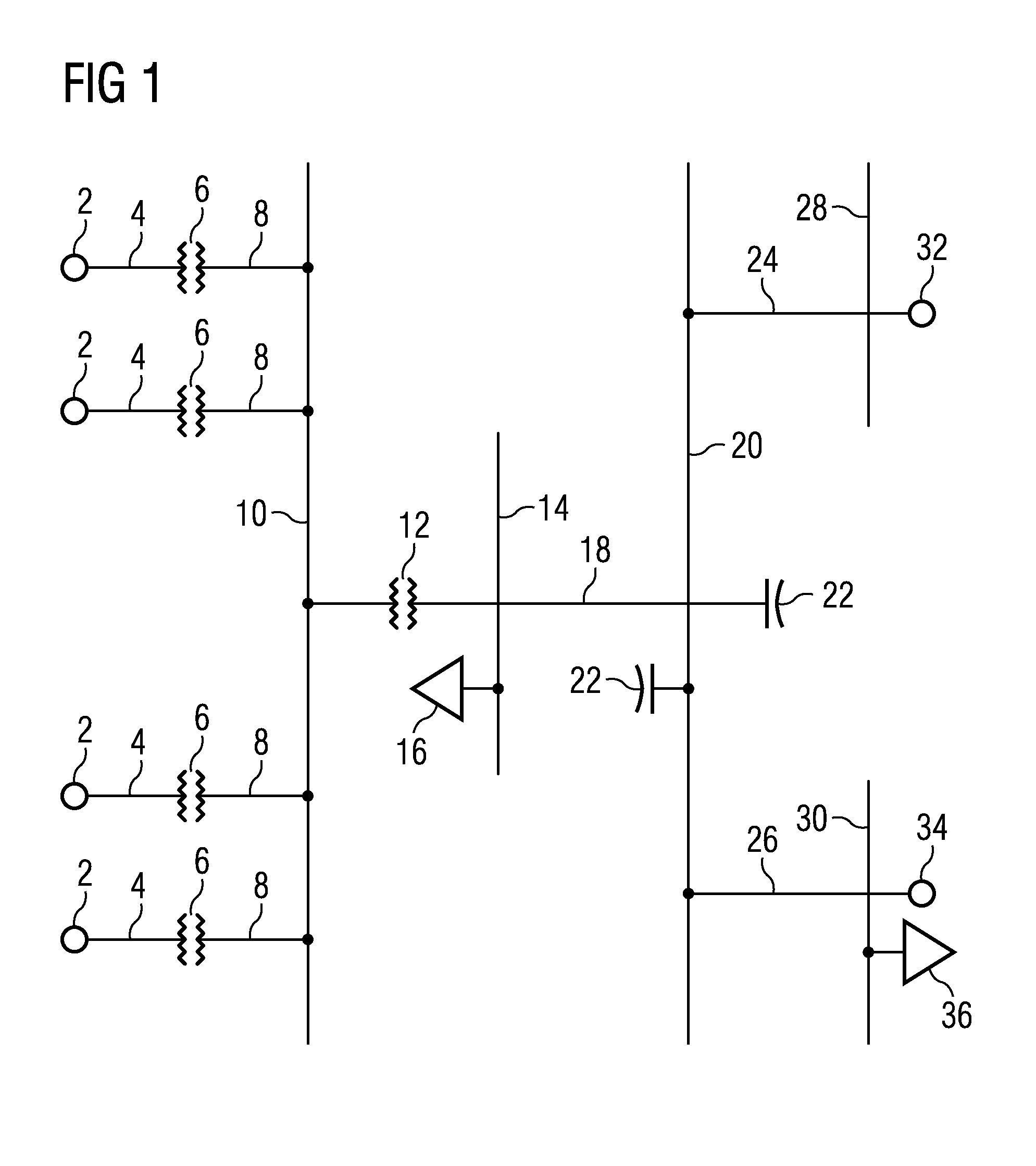
recovery method is particularly suitable if a plurality of power generating units is connected at a feeding point of a
power grid by weak power line or weak connection grid to the power system network. The advanced fault-ride-through and / or post fault active power
recovery method can be interpreted as a new and advanced control concept for power generating units for improving and ensuring the stability of the power network system, in particular in situations where a high number of power generating units are connected by a weak power line or connection grid of the power network to the power system network. The advanced fault-ride-through and / or post fault active power
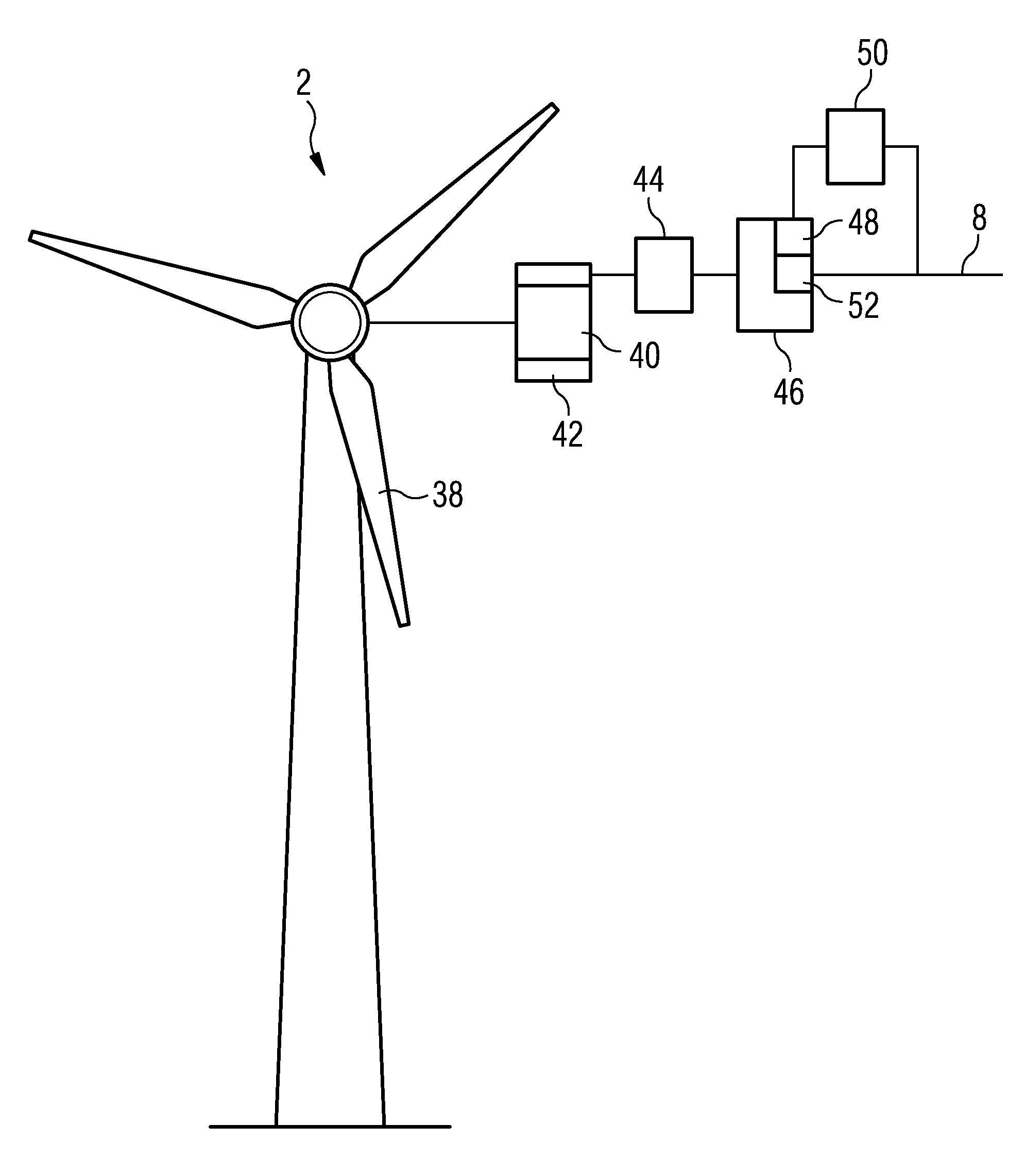
recovery method is particularly suitable for wind fauns, which in more and more cases are connected to weak grid systems, since more and more new large wind fauns are located in remote and sparsely populated areas. The wind farms may be located in rear and desolate areas or coast lines or off-
shore and thus remote from existing strong power network grids. The advanced fault-ride-through and / or post fault active power recovery method is also suited for power networks that do not have strong
interconnection grids for geographical reasons, such as rural and sparsely populated areas in Australia, New Zealand and Americas.
[0034]The advanced fault-ride-through and / or post fault active power recovery method increases the active current and / or the active
power over a pre-determined and / or
specific time period from a specific value when the voltage has regained normal operation conditions to the pre-fault value prior to the voltage-dip by a
specific function. In particular, the recovery of the post fault active current and / or the active power are increased essentially linearly. Thereby, the general post fault stability of the weak grid connected wind farm and generating units can be significantly improved.
[0036]Therefore, the invention also discloses a method of determining an appropriate fixed value by a method of simulating a fault-ride-through recovery event. Data of a power network, to which an aggregated power generating unit is to be connected, is provided. The data about the power network may comprise data of a connection grid or power line connecting a feeding point for a power generating unit to the power system network. Data of at least one aggregated power generating unit to be connected to the connection grid is provided. The data of the at least one aggregated power generating unit may comprise the impedance of the power generating unit, the maximum supplied power, complete
electrical control and data of the converter and the like. The fault-ride-through recovery may be simulated by simulating the voltages, currents, powers and / or the voltage-dip in the power network and the at least one aggregated power generating unit. It is not necessary to simulate the electric components and values of the entire power network. Typically, only data and electric values relating to
steady state and dynamic properties of the power line or connection grid connecting the feeding point to the remaining network has to be considered. The appropriate specific value of the active current and / or active power is depending on the properties of at least a part of the power network and determined by simulating the complete fault-ride-through and / or post fault sequence event. The appropriate specific value may be determined depending on the number of power generating units and generated active power production to be connected to a feeding point of the power network by simulating the fault-ride-through recovery. The appropriate specific value can be determined such that normal operation may be resumed within an acceptable time span without causing instabilities of at least a part of the power network and without risking unstable operation of the power generating units.

