Apparatus and Methods for Ion Mobility Spectrometry

a technology of ion mobility and apparatus, applied in the field of apparatus and methods for ion mobility spectrometry, can solve the problems of increasing separation length, reducing separation efficiency, and reducing separation efficiency,

Active Publication Date: 2012-06-21
THERMO FISHER SCI BREMEN
View PDF10 Cites 35 Cited by
  • Summary
  • Abstract
  • Description
  • Claims
  • Application Information

AI Technical Summary

Benefits of technology

[0034]Advantageously, the present invention addresses the problem of how to increase the ion mobility separation length within a limited space and with a simple construction. It can be seen that the invention in certain embodiments provides for at least two ion separation paths (i.e. ion trajectories) within one drift tube, preferably including one ion separation path which is a curved, more preferably helical, ion separation path. Such construction allows several unique modes of operation. One ion separation path, the curved or helical path for example, may provide a long separation path of high resolving power of ion mobility and lower speed. The at least one other path, which for example may be straight and for example may provide a shorter separation path of lower resolving power of ion mobility and higher speed than the helical path. The present invention in certain embodiments thus beneficially provides an ion mobility spectrometer having at least two ion separation paths of different length thereby enabling at least two different resolving powers and two different separation speeds, especially in a low field regime for the axial electric field. The invention accordingly further provides an ion mobility spectrometer and method of ion mobility spectrometry having switchable modes of speed and / or resolution. The drift tube itself is preferably straight not coiled and thus of simple construction compared to coiled drift tubes of the prior art.
[0035]The drift tube is preferably a straight drift tube and a high resolving power may beneficially be provided by a helical ion separation path within a straight drift tube wherein the drift tube is of similar length to a conventional straight drift tube, the length of the curved or helical ion separation path being substantially longer than the length of the drift tube. The invention thus enables a long separation path length, and hence high resolution of ion mobility separation, to be provided in a limited space.
[0037]Other advantages of the present invention include the possibility of rapid transfer of ions through the ion mobility spectrometer when no mobility separation is required. This could be used in combination with mobility separation, e.g. for adding internal calibrants to mobility-selected species.
[0053]In one mode of operation, a so-called transmission mode, ions are allowed to drift through the drift tube being pulled by the axial field but without ion mobility separation. In other words, the spectrometer thus acts as a simple ion guide in this transmission mode.

Problems solved by technology

Operation of the ion mobility spectrometer at lower pressures frequently leads to greater diffusion losses and lower resolution.
As increase of E is limited by low-field conditions and decrease of T is associated with cumbersome cryogenic techniques, it can be seen that the only way towards achieving higher R is to increase the separation length L. However, increasing the separation length can be problematic since space is typically limited.
However, construction of the drift tube becomes complex in that case and precludes rapid transfer of ions through the spectrometer in the case when no mobility separation is required.

Method used


Image

  • Apparatus and Methods for Ion Mobility Spectrometry
  • Apparatus and Methods for Ion Mobility Spectrometry
  • Apparatus and Methods for Ion Mobility Spectrometry

Examples


Embodiment Construction

[0060]In order to more fully understand the invention, it will now be described by way of example with reference to the accompanying Figures in which:

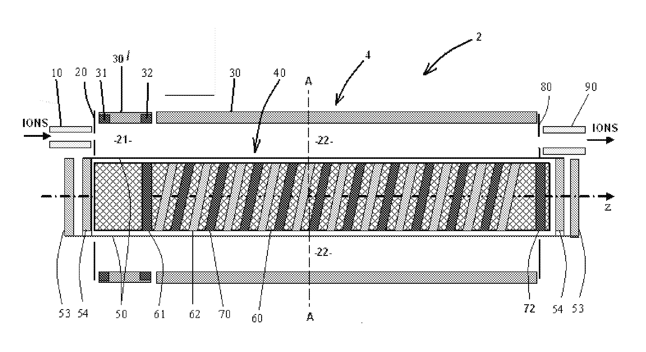
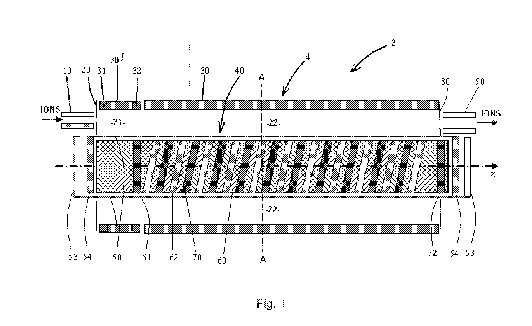
[0061]FIG. 1 shows schematically a side view, partly in cross section, of an embodiment of an ion mobility spectrometer according to the present invention taken on the line B-B shown in FIG. 2;

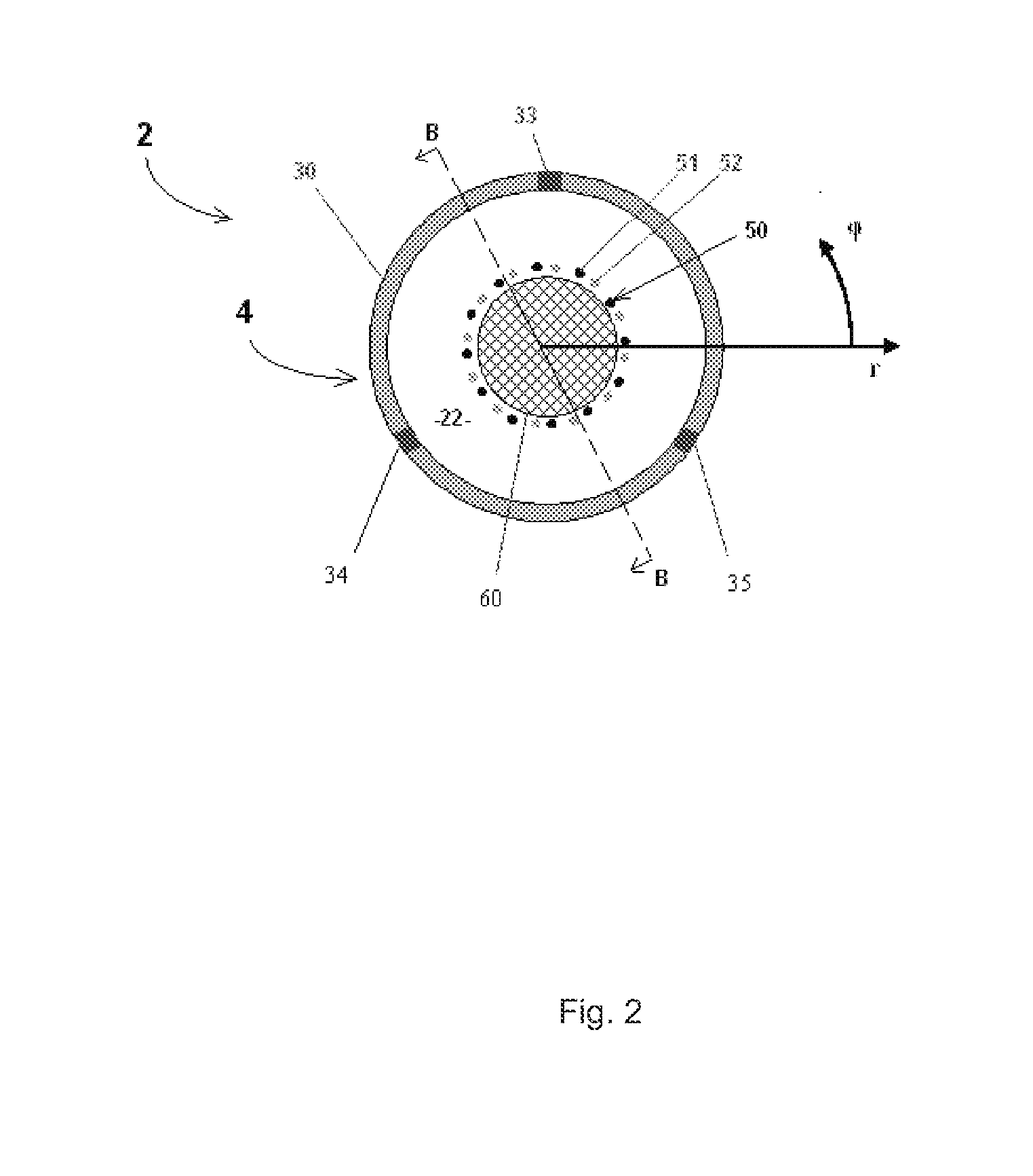
[0062]FIG. 2 shows schematically a transverse cross-sectional view of the embodiment shown in FIG. 1 taken on the line A-A;

[0063]FIG. 3 shows the DC voltage profile in the axial (z) direction within the ion mobility spectrometer in one embodiment of operation;

[0064]FIG. 4 shows the DC voltage profile in the arcuate (φ) direction within the ion mobility spectrometer in one embodiment of operation;

[0065]FIG. 5 shows potential profiles in the radial (r) direction for a sector in phase with an applied arcuate electric field in a high resolution filtering embodiment;

[0066]FIG. 6 shows potential profiles in the radial (r) direction for a sector out of ...


PUM


Abstract

There is provided of an on mobility spectrometer for separating ions according to their on mobility comprising, in various aspects: a drift tube having therein a drift space and in the drift space at least two on separation paths of different lengths: a straight drift tube having therein a helical ion separation path; a helical on separation path surrounding an axially extending inner electrode assembly; and a drift tube for separating ions according to their ion mobility wherein a rotating arcuate electric field is applied in operation to separate ions having an ion mobility such that their rotational velocity in the drift tube is matched to the rotational velocity of the rotating arcuate electric field. Various methods for separating ions according to their on mobility are also provided.

Description

FIELD OF THE INVENTION[0001]This invention relates to apparatus and methods for ion mobility spectrometry (IMS), including ion mobility spectrometers. The apparatus and methods may be suitable for use in combination with mass spectrometry (MS), e.g. in hybrid IMS / MS instruments.BACKGROUND OF THE INVENTION[0002]Known ion mobility spectrometers typically comprise a drift tube wherein ions are caused to drift under the influence of a constant applied electric field. Various constructions of drift tube have been proposed. The drift tube may, for example, comprise a series of ring electrodes axially spaced apart along the length of the spectrometer, wherein a constant potential difference is maintained between adjacent ring electrodes such that a constant electric field is produced in the axial direction. A pulse of ions is introduced into the drift tube, which contains a buffer gas, and as the ions travel through the tube under the influence of the constant electric field they attain a ...

Claims


Application Information

Patent Timeline
Patent Type & Authority Applications(United States)
IPC IPC(8): H01J49/36H01J49/26
CPCH01J49/004G01N27/622G01N27/623H01J49/009H01J49/062H01J49/06
Inventor MAKAROV, ALEXANDER A.
Owner THERMO FISHER SCI BREMEN
Why Eureka
Try Eureka