
Radiation measurement using timing-over-Ethernet protocol

a timing-over-ethernet protocol and radiation measurement technology, applied in the field of apparatus and methods for detecting radiation, can solve the problems of system limitation by time accuracy and precision, method is only practical for a small number of detectors, and cannot scale well to larger systems, so as to reduce complexity, accurate time information, and low cost

Inactive Publication Date: 2012-06-21
FLIR DETECTION
View PDF2 Cites 17 Cited by
  • Summary
  • Abstract
  • Description
  • Claims
  • Application Information

AI Technical Summary

Benefits of technology

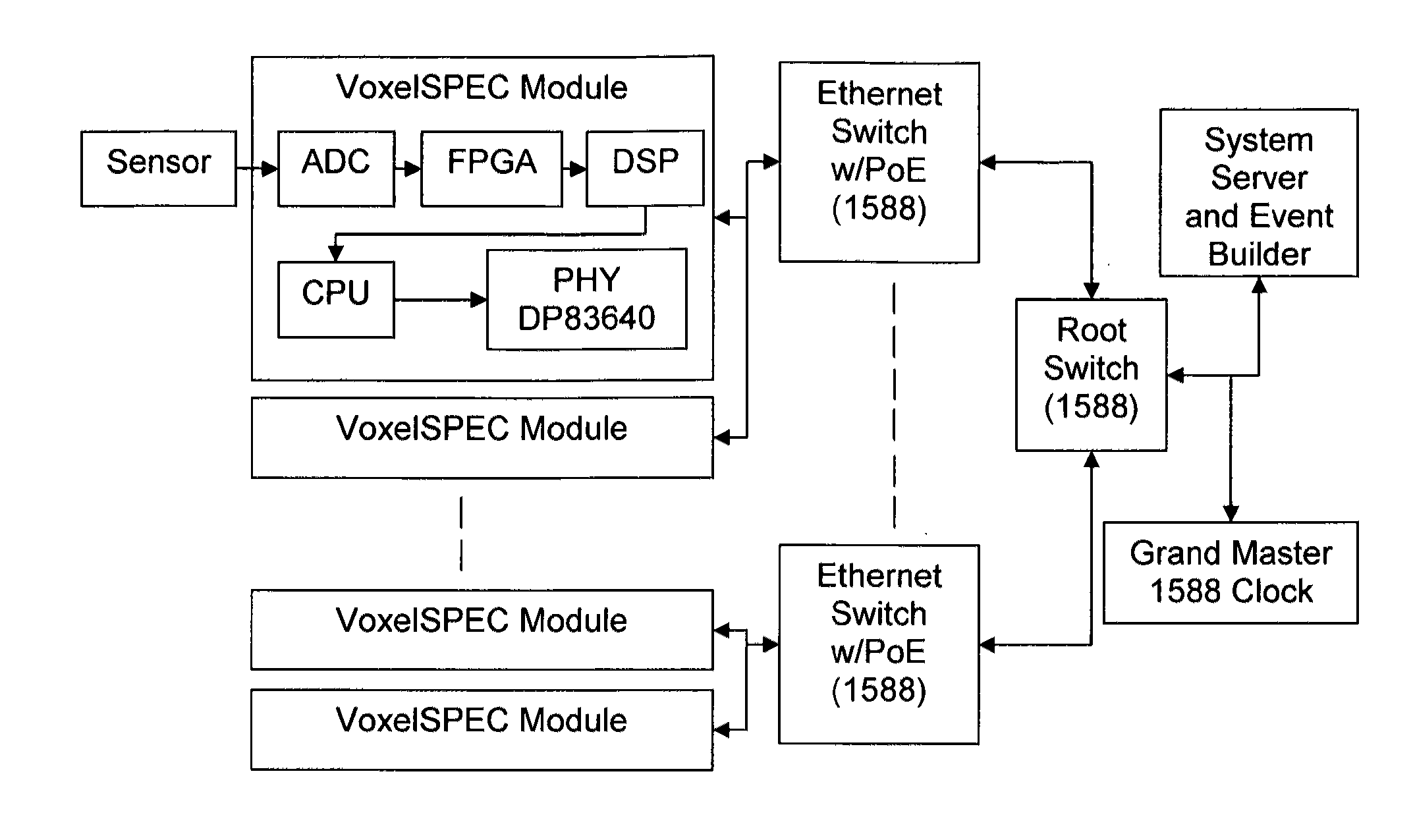
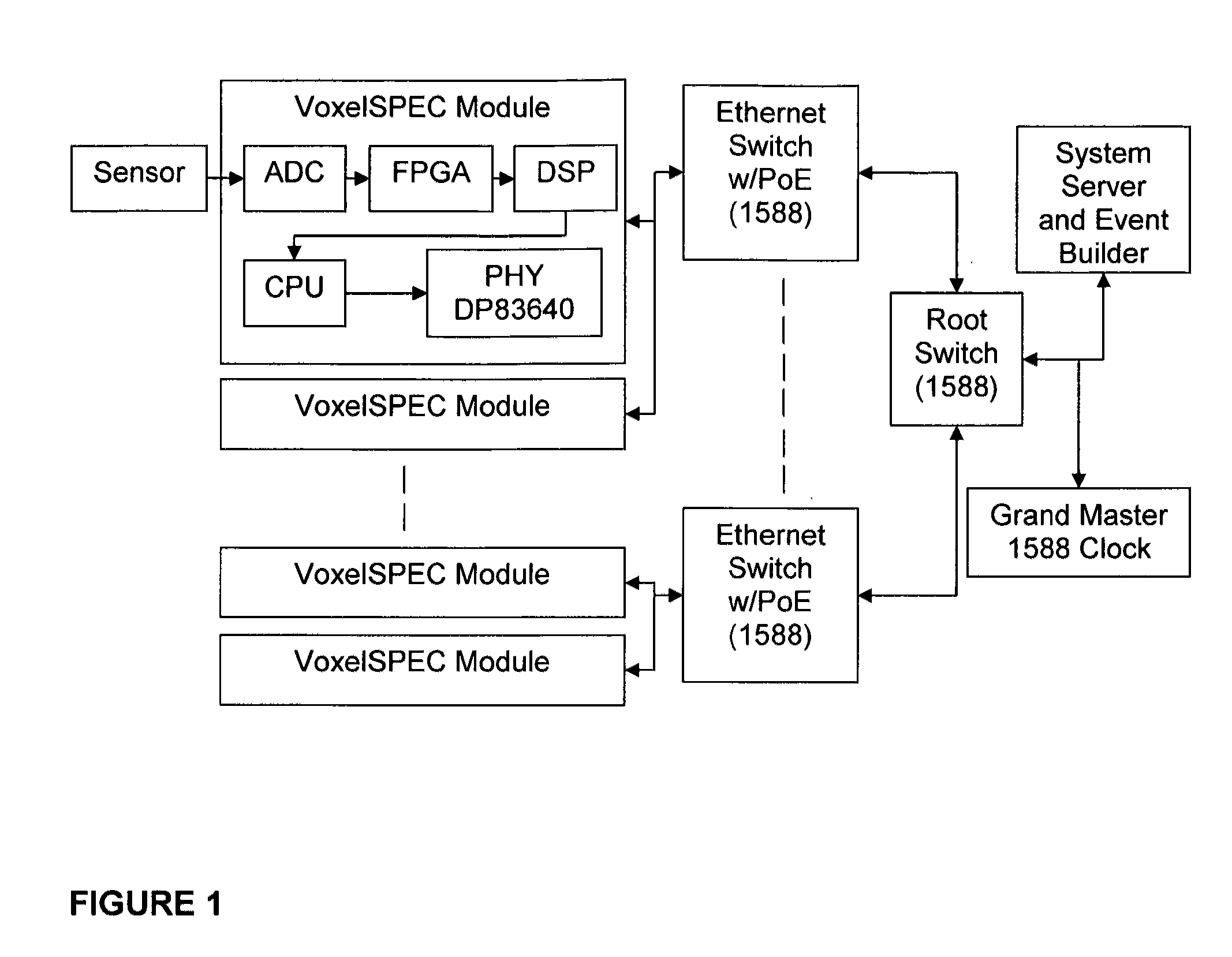
[0011]Objects of the present invention include the following: providing a large-scale radiation measurement system having reduced complexity; providing a large-scale radiation measurement system having relatively low cost; providing a large-scale radiation measurement system that provides accurate time information for each event and each system element; providing a large-scale radiation measurement system that requires low power; providing a large-scale radiation measurement system in which synchronization and time measurement is provided by a network protocol and not by hardware; providing a large-scale radiation measurement system requiring only one cable to be connected through a switch to t

Problems solved by technology

This method is only practical for a small number of detectors, usually limited to only two, and does not scale well to larger systems.
However, this system is limited by the accuracy and precision of the time synchronization of the individual detector electronics that generate the time stamps.
While this method is adaptable for large systems, it must be designed for the specific system and is not easily scalable.
Designers of several large physics experiments have independently developed methods of generating the timestamps and for distributing the clock signals in order to synchronize the units, showing that the technology is not scalable or portable.
This can be problematic as most radiation induced events have low signal levels which can be easily dominated by noise.

Method used


Image

  • Radiation measurement using timing-over-Ethernet protocol
  • Radiation measurement using timing-over-Ethernet protocol
  • Radiation measurement using timing-over-Ethernet protocol

Examples


example

[0051]Time synchronization is critical to the performance of a large Compton telescope array. Large arrays require efficient background suppression that may be performed by discriminating incoming events according to a coincidence time window. The start event occurs at the scattering plane and the stop event occurs at the absorption plane. This window is a function of each detector's response time characteristics, signal processing parameters, and variance of the absolute time of the clock used to time stamp events.[0052]Detectors of the front and back planes are chosen for fast response and are coupled to electronics with minimal signal processing delays that are designed to have minimal contribution to the timing variance. Each node in the array consists of an independent signal processing unit that is capable of simultaneously determining pulse height and time of each event. Events are processed using a FPGA to extract the timing information from the rise time of the detector's c...


PUM


Abstract

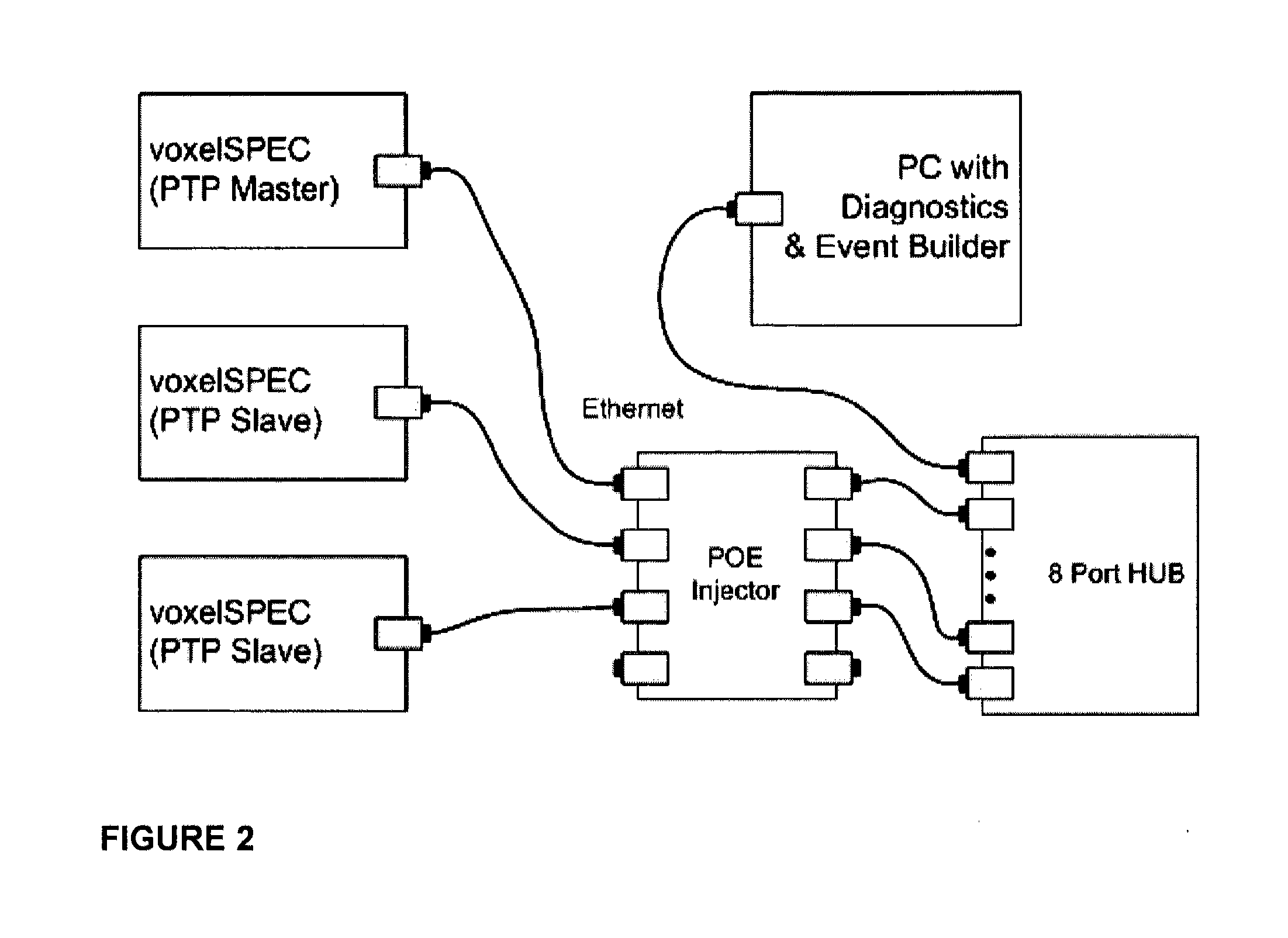
A highly scalable platform for radiation measurement data collection with high precision time stamping and time measurements between the elements in the detection array uses IEEE 1588 with or without Synchronous Ethernet (timing over Ethernet) to synchronize the measurements. At a minimum, the system includes at least two radiation detector units, an IEEE 1588 and SyncE enabled Ethernet switch, and a computer for processing. The addition of timing over Ethernet and power over Ethernet (PoE) allows a radiation measurement system to operate with a single Ethernet cable, simplifying deployment of detectors using standardized technology with a multitude of configuration possibilities. This eliminates the need for an additional hardware for the timing measurements which simplifies the detection system, reduces the cost of the deployment, reduces the power consumption of the detection system and reduces the overall size of the system.

Description

CROSS-REFERENCE TO RELATED APPLICATIONS[0001]This application claims the benefit of U.S. Provisional Application Ser. No. 61 / 395,424 entitled Radiation Measurement Using Timing-Over-Ethernet Protocol, filed by the present inventors on May 13, 2010, the entire disclosure of which is incorporated herein by reference.STATEMENT REGARDING FEDERALLY SPONSORED RESEARCH[0002]This invention was made with Government support under Contract No. HDTRA1-09-C-0012 awarded by the U.S. Defense Threat Reduction Agency to ICx Radiation, Inc., and the Government has certain rights in this invention.BACKGROUND OF THE INVENTION[0003]1. Field of the Invention[0004]The invention pertains to apparatus and methods for detecting radiation, and more particularly to radiation detectors that rely on measuring the time between detection events to obtain useful information.[0005]2. Description of Related Art[0006]Radiation is typically measured by detecting an electrical pulse that is generated through an interact...

Claims


Application Information

Patent Timeline
IPC IPC(8): G01T1/20G01T1/18G01T1/185G01T1/00G01T1/24
CPCG01T1/172H04J3/0667G01T7/00
Inventor GUEORGUIEV, ANDREY K.OHMES, MARTIN F.PRESTON, JEFFREY R.HOY, LESLIE D.BRANDS, HARTMUT
Owner FLIR DETECTION
Learn More