Radiation image capturing apparatus and radiation image obtaining method

a radiation image and capturing apparatus technology, applied in the field of radiation image obtaining method and radiation image capturing apparatus, can solve the problems of insufficient contrast as x-ray transmission image, low x-ray absorption power of substances constituted by elements, atomic number, etc., and achieve satisfactory phase contrast image, reduce radiation incident on the first and second grid, and satisfactory contrast image

Inactive Publication Date: 2012-06-21
FUJIFILM CORP
View PDF5 Cites 14 Cited by
  • Summary
  • Abstract
  • Description
  • Claims
  • Application Information

AI Technical Summary

Benefits of technology

[0048]According to the present invention, in a radiation image capturing apparatus which includes first and second grids and a radiation image detector, a position of the radiation image detector in an in-plane direction of a detection plane of the detector is made adjustable by a detector positioning mechanism such that radiation transmitted through the first and second grids falls within the radiation image detector. This allows a radiation range of the radiation transmitted through the first and second grids on the radiation image detector to fall with in the detection plane even when, for example, the size of the radiation image detector is changed or positions of the first and second grids are changed. Thus, radiation transmitted through the first and second grids may be detected by the radiation image detector without loss and a more satisfactory contrast image may be obtained.
[0049]Further, the first and second grids are configured to be removably attachable and positions of the first and second grids are adjusted such that a radiation center of the radiation transmits through the centers of the first and second grids substantially perpendicularly. This allows the vignetting of radiation incident on the first and second grids may be reduced even when, for example, the sizes of the first and second grids are changed and a more satisfactory phase contrast image may be obtained.
[0050]In the case in which the position of the radiation image detector is adjusted such that a radiation range of the radiation transmitted through the first and second grids on the radiation image detector falls in the center of the radiation image detector, an area of the detection surface of the radiation image detector where image unevenness is not likely to occur may be used, whereby the image quality may be improved.
[0051]It is also preferable that the area of the radiation image detector from which image signals are read out is limited to a central area to reduce the signal readout time. The reason is that some subjects can not keep still for a prolonged time and if the image capturing operation is not performed in a short time, an image blur is likely to occur due to displacement (body motion) or sway of the subject. If such image blur occurs during the image capturing operation, the contrast or resolution of a reconstructed phase contrast image may be degraded. But, this arrangement allows reduction in the image blur and acquisition of a satisfactory phase contrast image.

Problems solved by technology

However, the X-ray absorption power is low for a substance constituted by an element with a small atomic number in comparison with a substance constituted by an element with a high atomic number.
As such, the difference in X-ray absorption power is small in soft biological tissues and soft materials, thereby causing a problem of insufficient contrast as an X-ray transmission image.
For example, the articular cartilage and synovial fluid constituting a joint of a human body consist mostly of water and the difference in the amount of X-ray absorption between them is small, thereby resulting in a low image contrast.
Heretofore, such soft-tissue portions may have been imaged by MRI, but the MRI imaging has problems of a long imaging time of several tens of minutes, a low image resolution of about 1 mm, and a low cost-effectiveness that makes it difficult to perform MRI imaging at regular physical examinations such as health checkups.
X-ray phase contrast imaging may also have been possible by monochromatic X-rays with well-aligned phase generated from a large scale radiation facility (e.g., SPring-8, Hyogo, JAPAN) or the like, but such a radiation facility is too large to be available in a general hospital.
Further, the X-ray phase contrast imaging may image cartilages and soft-tissue portions which is difficult to be observed in X-ray absorption contrast images as described above.
But, the pixel pitch of the radiation image detector is typically several tens to hundreds of micrometers, which makes it difficult to directly measure the positional displacement.
But when the intensity of the radiation is decreased after transmitting through the grids, the signal to noise ratio (S / N ratio) of the moiré fringe images is degraded, thereby causing calculation errors which may lead to significant degradation in the contrast and resolution of the phase contrast image.
In the case where the aforementioned radiation imaging cassettes of different sizes are used in conjunction with the first and second grids disposed in the manner as described above, radiation transmitted through the first and second grids may be extended beyond the detector or concentrated in the corner depending on the size thereof as the sizes of the grids are small relative to the sizes of the radiation image detectors, thereby causing a problem of inappropriate phase contrast image.
The same problem may occur when the two diffraction grids and radiation source are moved according to the position of the subject, not just when the radiation image detector is replaced with another having different size.
Japanese Unexamined Patent Publication No. 2004-147917 describes that the radiation image detector is moved according to the movement of the radiation source, but does not consider at all the problem of vignetting of radiation by the first and second grids, use of cassettes of different sizes, and the problem that there may be a case in which radiation transmitted through the grids is extended beyond the detector.

Method used


Image

  • Radiation image capturing apparatus and radiation image obtaining method
  • Radiation image capturing apparatus and radiation image obtaining method
  • Radiation image capturing apparatus and radiation image obtaining method

Examples


second embodiment

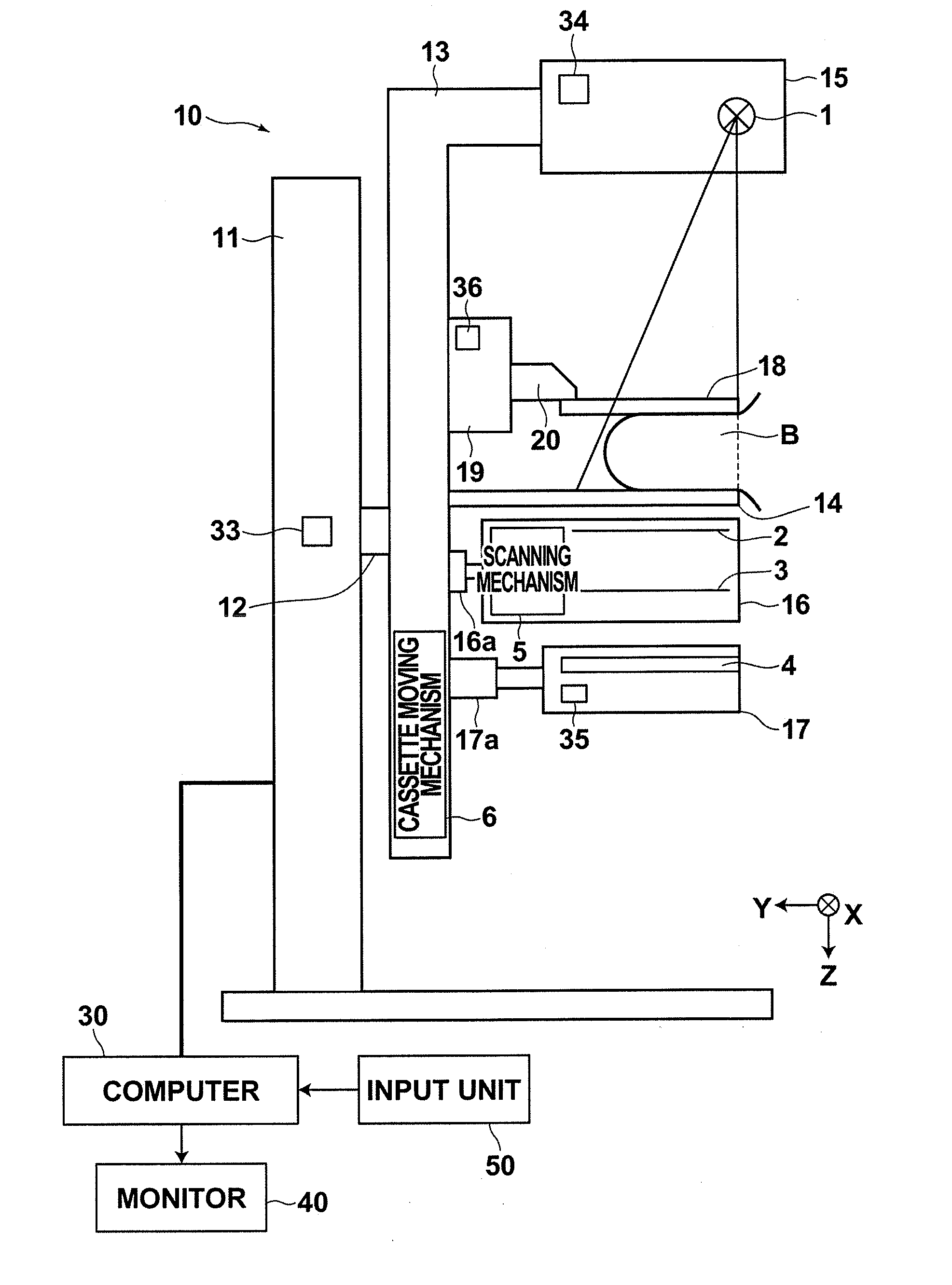
[0179]Computer 30 of the second embodiment includes grid position control unit 60b and grid information obtaining unit 63, as illustrated in FIG. 17.

[0180]Grid position control unit 60b causes grid moving mechanism 7 provided in arm 13 to move grid unit 16 in X-Y directions by outputting a control signal to grid moving mechanism 7 based on grid information obtained by grid information obtaining unit 63. More specifically, grid position control unit 60b includes therein a preset table that relates grid information to movement amounts of grid unit 16 in X-Y directions as shown in FIG. 18. Grid position control unit 60b receives grid information, refers to the table based on the received grid information to obtain a movement amount corresponding to the grid information, and outputs a control signal according to the movement amount to grid moving mechanism 7. Note that the movement amounts are those of grid unit 16 from a predetermined default position thereof.

[0181]In the present embod...

first embodiment

[0191]Then, after the position of grid unit 16 is adjusted in the manner as described above, a phase contrast image capturing operation is initiated (S38, S40). The operation for capturing the phase contrast image is identical to that of the first embodiment described above.

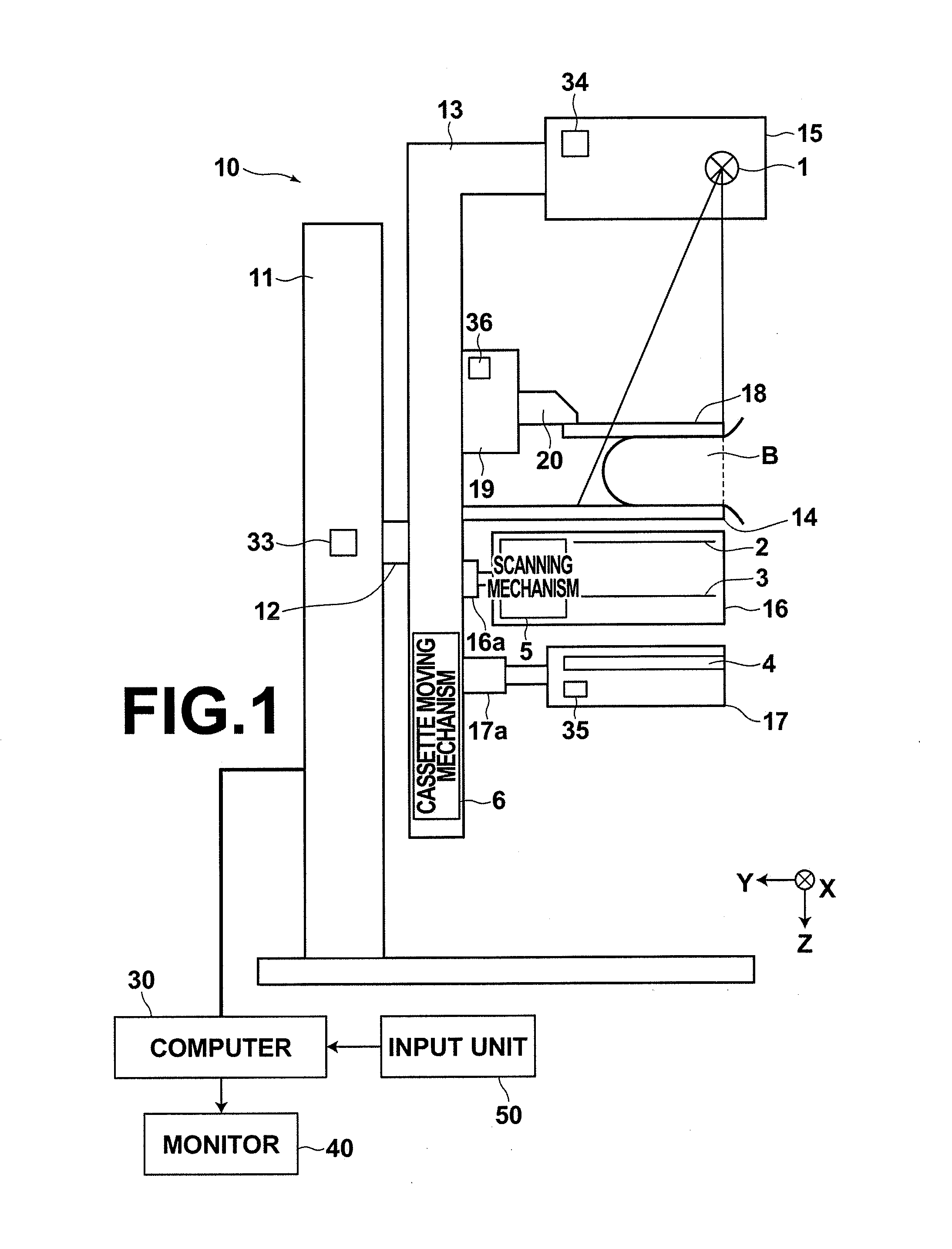
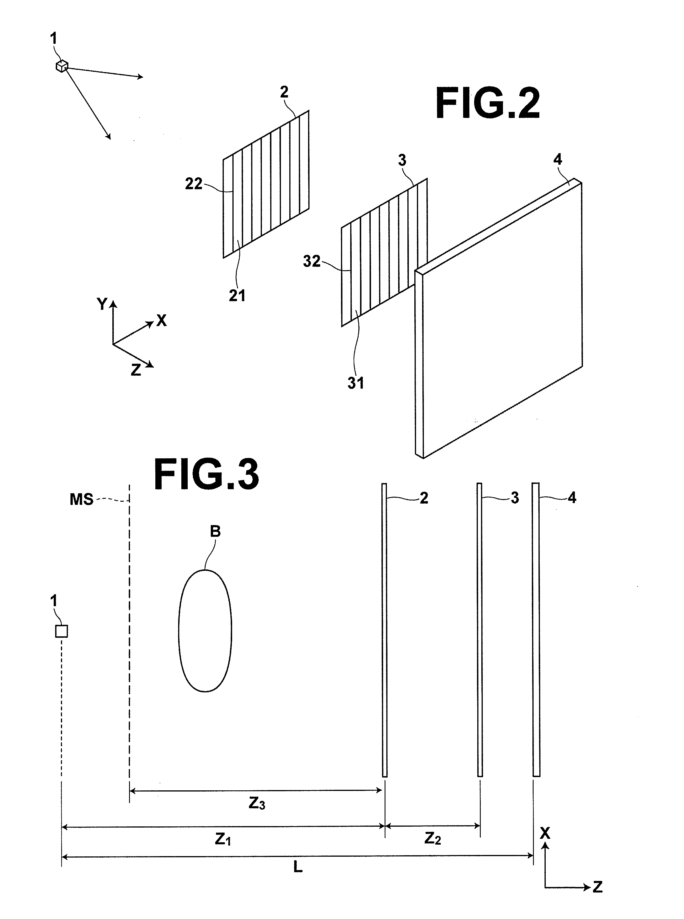
[0192]In the breast image capturing and display system of the first embodiment, the cassette unit 17 is configured to be movable and in the breast image capturing and display system of the second embodiment, the grid unit 16 is configured to be movable. But an arrangement may be adopted in which both the cassette unit 17 and grid unit 16 are configured to be movable. In this case, the cassette unit 17 and grid unit 16 may be move relative to each other such that radiation transmitted through first grid 2 and second grid 3 in grid unit 16 is incident on the center of radiation image detector 4 in cassette unit 17.

[0193]Further, in breast image capturing apparatus 10 of the breast image capturing and display system...


PUM


Abstract

A radiation image capturing apparatus includes: a first grid which includes grid structures disposed at intervals and forms a first periodic pattern image by passing radiation emitted from a radiation source; a second grid provided with grid structures disposed at intervals and forms a second periodic pattern image by receiving the first periodic pattern image; a radiation image detector that detects the second periodic pattern image formed by the second grid; and a detector positioning mechanism that adjusts a position of the radiation image detector in an in-plane direction of a detection plane of the detector such that radiation transmitted through the first and second grids falls within the radiation image detector.

Description

BACKGROUND OF THE INVENTION[0001]1. Field of the Invention[0002]The present invention relates to a radiation image obtaining method and a radiation image capturing apparatus using a grid.[0003]2. Description of the Related Art[0004]X-rays are used as a probe for looking through the inside of a subject as they attenuate, when passing through a substance, according to the atomic number of the element constituting the substance, as well as the density and thickness of the substance. X-ray imaging is widely used in the fields of medical diagnosis, nondestructive inspection, and the like.[0005]In a general X-ray imaging system, a transmission image of a subject is captured by placing the subject between an X-ray source that emits X-rays and an X-ray image detector that detects X-ray images. In this case, each X-ray emitted from the X-ray source toward the X-ray image detector is incident on the X-ray detector after being attenuated (absorbed) by an amount corresponding to a difference in...

Claims


Application Information

Patent Timeline
Patent Type & Authority Applications(United States)
IPC IPC(8): G01T1/16
CPCA61B6/4291A61B6/4452A61B6/547A61B6/502A61B6/484
Inventor IWAKIRI, NAOTOMURAKOSHI, DAI
Owner FUJIFILM CORP
Why Eureka
Try Eureka