
System, method and facility optimized for increasing patient throughput and scan efficiency

Inactive Publication Date: 2012-06-21
GENERAL ELECTRIC CO
View PDF3 Cites 12 Cited by
  • Summary
  • Abstract
  • Description
  • Claims
  • Application Information

AI Technical Summary

Benefits of technology

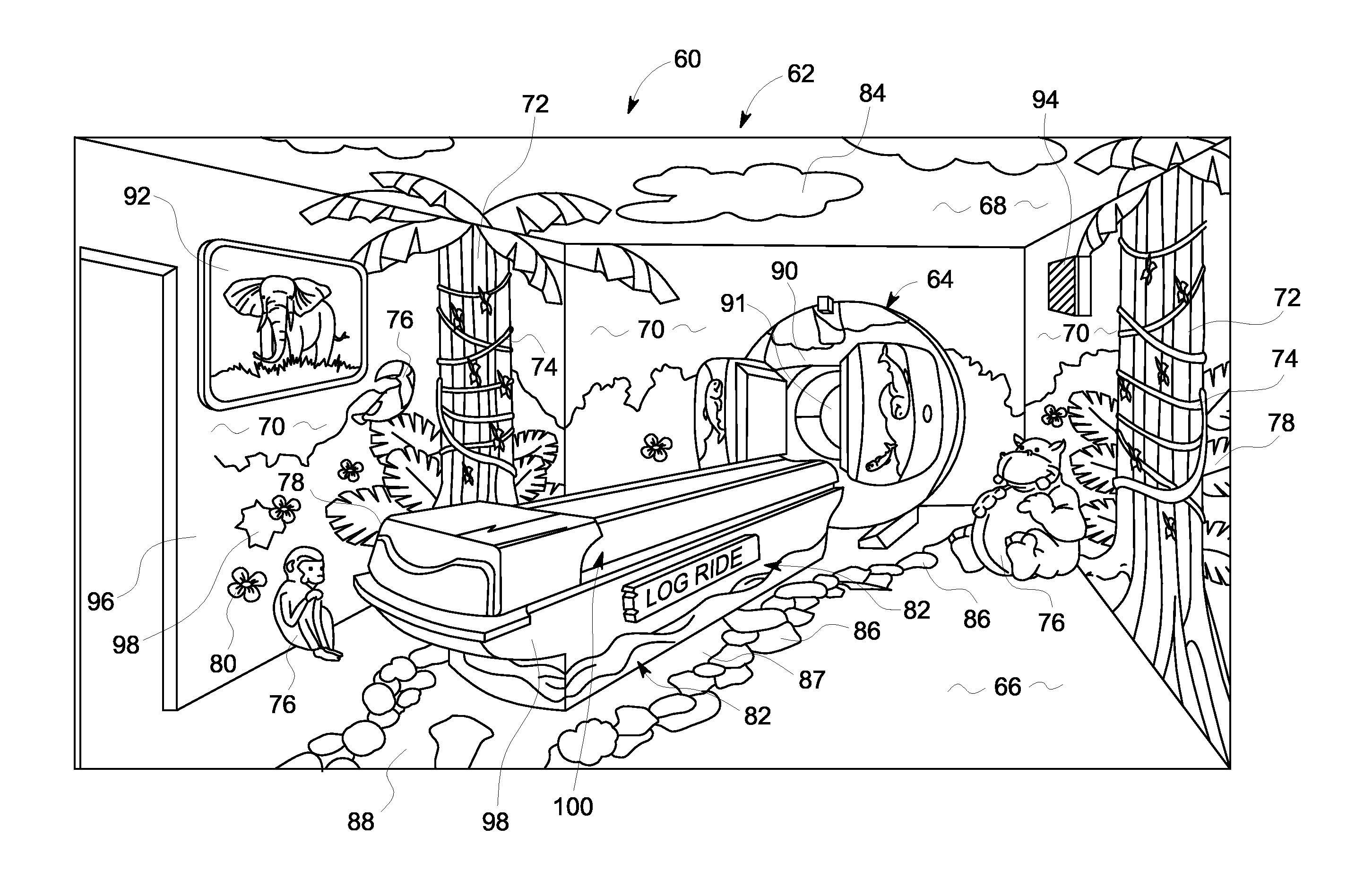
[0010]In one embodiment, a facility for performing a medical imaging procedure includes a room having a medical imaging system located in the room, and a plurality of inventive thematic elements installed on the room walls, ceiling, floor, and the medical imaging system. The thematic elements collectively create a theme that forms a physical environment and includes the imaging equipment that at least partially surrounds the patient, wherein the theme is presented in a manner to reduce the level of patient anxiety and fear experienced by the child / patient being imaged to increase patient throughput.
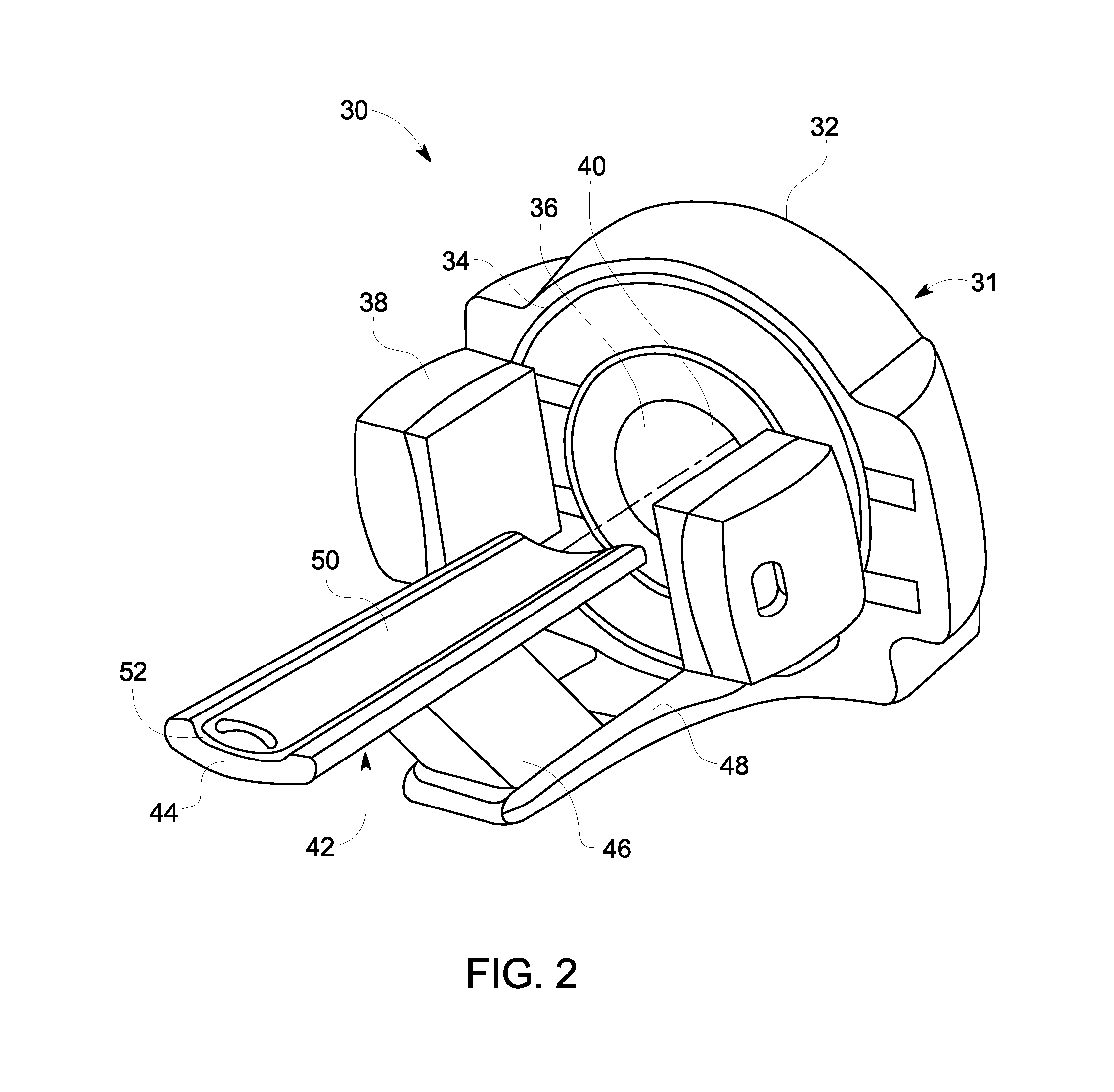
[0011]In another embodiment, a medical imaging system is provided. The medical imaging system includes a medical imaging device, an imaging table adapted to support and / or move the patient with respect to the medical imaging device, and a plurality of thematic elements installed on the medical imaging device including the table. The thematic elements collectively creating a theme that forms a physical environment with the imaging room at least partially surrounding a patient, wherein the theme is presented in a manner to reduce the level of patient anxiety and fear experienced by the patient being imaged to increase patient throughput.
[0012]In another embodiment, a method of remodeling an existing medical imaging facility to reduce patient anxiety is provided. The method includes selecting a room in the medical imaging facility, determining a theme to be installed in the selected room, and modifying the selected room based on the determined theme, wherein the selected theme is presented in a manner to reduce the level of patient anxiety and fear experienced by the patient being imaged to increase patient throughput.

Problems solved by technology

Medical images constructed (or reconstructed) from data acquired by the medical imaging equipment and / or systems are deleteriously affected by patient motion during the data acquisition phase and is a well known problem.
This inefficiency is not merely burdensome and increasingly more traumatic for the child, it is a poor use of hospital resources, equipment and staff.
However, involuntary motion encountered in medical imaging systems is also common and a source of image artifacts, and may be caused by numerous physiological parameters.
Increased patient anxiety is known to cause increases in some of the patient's involuntary physiological parameters such as the patients breathing or the patient's heart rate, resulting in increased patient movement during imaging.
This pediatric patient anxiety is often attributable to the intimidating look and overall appearance of the imaging system as viewed through the child's eyes regardless of the modality.
While both the conventional imaging system and the conventional imaging system room are designed to improve the performance of the imaging system and to enhance the operation of the system by the medical personnel, the clinical appearance and smell, the unfamiliar shape and large size of the equipment, and associated operational sounds of it, etc., are known to cause anxiety and fear in pediatric patients undergoing the medical imaging procedure.
In turn, the anxiety and fear exhibited by the child is manifested in both voluntary and involuntary motion including, but not limited to, elevated heart rates, rapid breathing, fidgeting, trembling, and nervousness resulting in unwanted body movement during image data capture, thereby prolonging the time it takes ton acquire a successful scan which equates to a reduction in patient throughput.
While sedative injections or inhalants used for children are common in imaging procedures they are wholly undesirable.

Method used


Image

  • System, method and facility optimized for increasing patient throughput and scan efficiency
  • System, method and facility optimized for increasing patient throughput and scan efficiency
  • System, method and facility optimized for increasing patient throughput and scan efficiency

Examples


Embodiment Construction

[0028]The foregoing summary and detailed description of certain embodiments of the present invention will be better understood when read in conjunction with the appended drawings. To the extent that the figures illustrate diagrams of the functional blocks of various embodiments, the functional blocks are not necessarily indicative of the division between hardware circuitry. Thus, for example, one or more of the functional blocks (e.g., processors or memories) may be implemented in a single piece of hardware (e.g., a general purpose signal processor or a block of random access memory, hard disk, or the like). Similarly, the programs may be stand alone programs, may be incorporated as subroutines in an operating system, may be functions in an installed software package, and the like. It should be understood that the various embodiments are not limited to the arrangements and instrumentality shown in the drawings.

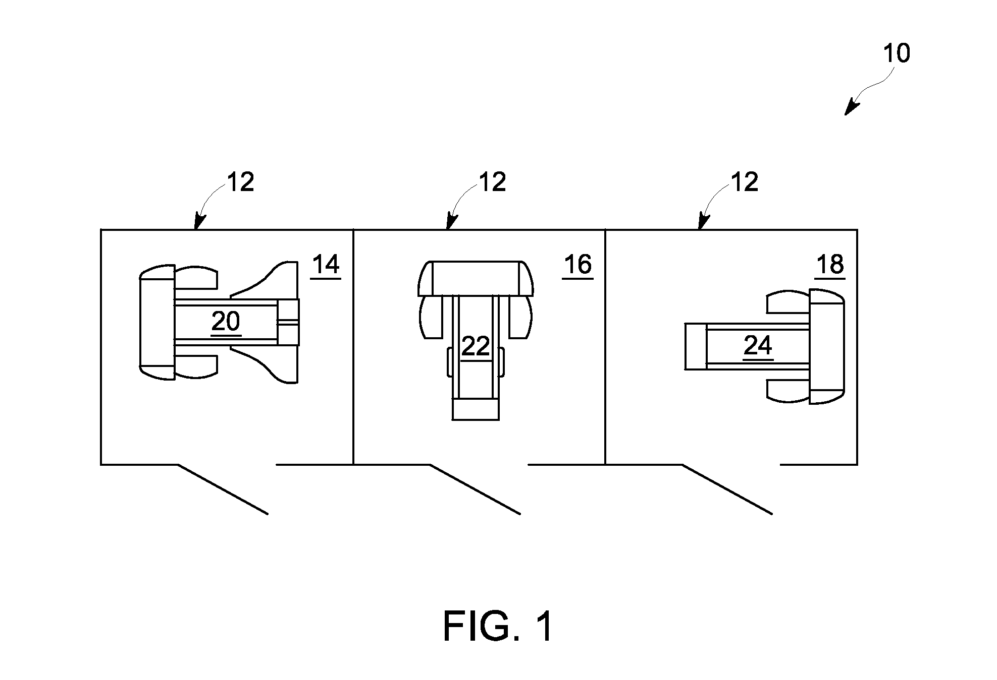
[0029]FIG. 1 is a top view of an exemplary medical imaging facility 10 in...


PUM


Abstract

A facility for performing a medical examination includes a room, a medical imaging system located in the room, and a plurality of elements installed on at least one of the room and the medical imaging system, the elements collectively creating a first theme that forms a physical environment at least partially surrounding a patient, wherein the theme is presented in a manner to increase the throughput of imaging patients while increasing overall patient satisfaction by reducing the level of patient anxiety and fear experienced by the patient being imaged. A compatibly configured medical imaging system is also described.

Description

BACKGROUND OF THE INVENTION[0001]The present invention relates generally to medical imaging systems, and more particularly to a method and system for reducing the anxiety level of a patient, particularly a pediatric patient, before and during the procedure in order to further reduce image artifacts attributable to patient motion during image data capture. In so doing, the present invention is designed to increase patient throughout from one patient to the next by increasing the scan efficiency due to a reduction of the overall combined time associated with a comparative collection of patient scans without the present invention.[0002]Medical imaging systems scan patients to obtain medical information, and involve several imaging modalities, including: computed tomography (“CT”), positron emission tomography (“PET”), combined CT and PET (“PET-CT”), single photon emission computed tomography (“SPECT”), X-ray, gamma camera imaging, magnetic resonance (“MR”), and others, including the co...

Claims


Application Information

Patent Timeline
IPC IPC(8): A61M21/02
CPCA61M21/0094A61M21/02A61M2205/59A61M2021/005A61M2021/0027
Inventor DIETZ, DOUGLAS PENROSE
Owner GENERAL ELECTRIC CO
Learn More