Luminescent Solar Energy Concentrator With A New Architecture

a solar energy concentrator and solar energy technology, applied in the field ofluminescent concentrators, can solve the problems of poor efficiency of light coupling into the waveguide, high re-absorption of emitted light, and poor efficiency of the luminescent concentrator presently, and achieve the effect of reducing re-absorption losses

Inactive Publication Date: 2012-06-28
SIGNIFY HLDG BV
View PDF8 Cites 2 Cited by
  • Summary
  • Abstract
  • Description
  • Claims
  • Application Information

AI Technical Summary

Benefits of technology

[0007]It is therefore an object of the present invention to provide a luminescent concentrato

Problems solved by technology

However, these luminescent concentrators presently show poor efficiency originating from a high re-absorption of the emitted light, from a poor efficiency of coupling light into the waveguide and from a poor efficiency in keeping the light within the waveguide.
However, again re-absorption of converted light strongly contributes to energy losses in these luminescent concentrators.
The optical gain

Method used


Image

  • Luminescent Solar Energy Concentrator With A New Architecture
  • Luminescent Solar Energy Concentrator With A New Architecture

Examples


Embodiment Construction

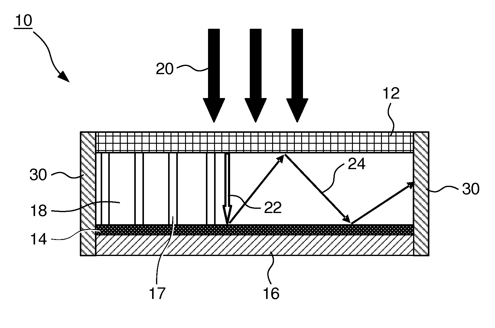
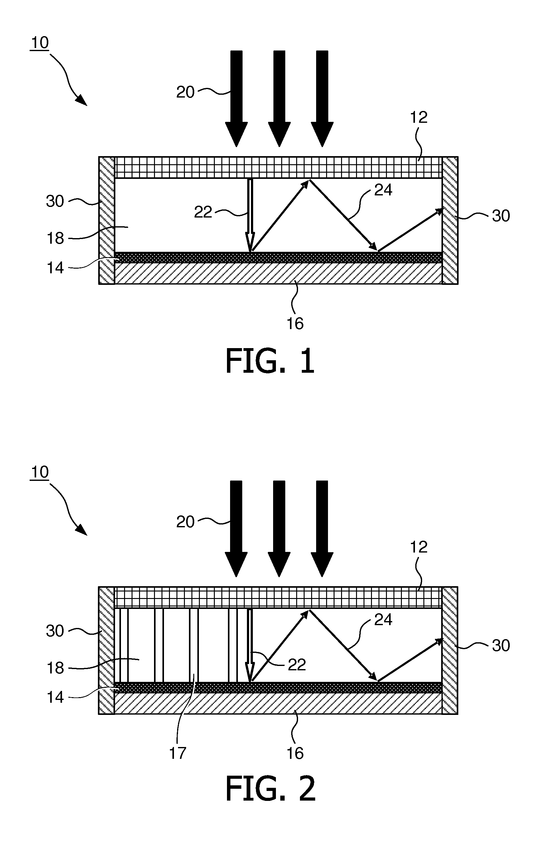
[0044]FIG. 1 schematically shows a configuration of an embodiment of a luminescent concentrator 10. The luminescent concentrator 10 comprises a wavelength-selective filter 12, a luminescent material 14 and an energy concentrating area 18, for example an air gap, therebetween. In the embodiment, the filter 12 is arranged at the top of the concentrator 10 so that incident solar light 20 can optimally reach the filter 12. A part of the incident solar light 22 passes through the filter 12 and the area 18 onto and / or into the luminescent material 14. This part 22 is absorbed by the luminescent material 14 and converted to converted light 24. For example, a large Stokes Shift between absorbed light 22 and emitted / converted light 24 may be provided so that the converted light 24 provides for a larger wavelength than the solar light 22. The converted light 24 is then concentrated in the area 18 between the filter 12 and the luminescent material 14. In particular, a reflective structure 16 m...


PUM


Abstract

A luminescent concentrator for solar light is provided. The luminescent concentrator comprises a wavelength-selective filter, an energy concentrating area, and a luminescent material. The wavelength-selective filter is adapted to pass the solar light and to reflect light emitted by the luminescent material. Further, a method for concentrating solar light is provided. The method comprises the steps of (a) passing incident solar light through a wavelength-selective filter and an energy concentrating area onto a luminescent material, and (b) converting the incident solar light in the luminescent material to light having a wave-length reflectable by the wavelength-selective filter. The method further comprises a step (c) of concentrating the converted light in a pre-determined area arranged between the wavelength-selective filter and the luminescent material.

Description

TECHNICAL FIELD OF THE INVENTION[0001]The invention relates to a luminescent concentrator. For example, the luminescent concentrator may be used in connection with solar energy in order to concentrate incident solar light for subsequent conversion in a photovoltaic system.BACKGROUND OF THE INVENTION[0002]In order to reduce the costs of solar energy generation in photovoltaic systems, it is desirable to make efficient use of the most expensive part of the system, namely the photovoltaic cell (for example, by providing increased current generation by using larger light fluxes). Conventionally, this is done by using large light-focusing solar concentrators.[0003]For example, luminescent solar concentrators are used in connection with waveguides in this technical field. Basically, these luminescent concentrators consist of a large glass plate doped with fluorescent dye molecules. The dyes absorb light of specific wavelengths from the solar light incident upon it, and re-emit the light i...

Claims


Application Information

Patent Timeline
IPC IPC(8): H01L31/055F24S23/79
CPCY02E10/52H01L31/055G01J1/0422G02B6/42
Inventor RONDA, CORNELIS REINDERDE BOER, DIRK KORNELIS GERHARDUS
Owner SIGNIFY HLDG BV
Why Eureka
Try Eureka