Substrate processing apparatus and substrate processing method

a substrate processing and substrate technology, applied in the direction of electrical equipment, electrical discharge tubes, decorative arts, etc., can solve the problems of inability to freely control the temperature of the focus ring may also fluctuate, and the in-plane process characteristics of the substrate cannot be controlled by certain processes

Inactive Publication Date: 2012-06-28
TOKYO ELECTRON LTD
View PDF7 Cites 39 Cited by
  • Summary
  • Abstract
  • Description
  • Claims
  • Application Information

AI Technical Summary

Benefits of technology

[0011]The present invention provides a substrate processing apparatus etc., where the temperature of a focus ring is independently controlled from the temperature of a substrate, thereby freely controlling in-plane process characteristics of the substrate.
[0013]Accordingly, the substrate is electrostatically adsorbed to the substrate holding surface of the substrate holding unit while the focus ring is electrostatically adsorbed to the focus ring holding surface. Furthermore, by independently providing the first heat transfer gas supply unit supplying the first heat transfer gas to the rear surface of the substrate and the second heat transfer gas supply unit supplying the second heat transfer gas to the rear surface of the focus ring, the second heat transfer gas may be supplied to the rear surface of the focus ring independently from the first heat transfer gas supplied to the rear surface of the substrate. Thus, thermal conductivity of the temperature controlled susceptor may be independently changed to independently control the temperature of the focus ring and the temperature of the substrate, thereby improving or freely controlling in-plane process characteristics of the substrate.
[0017]In this case, a plurality of protruding portions supporting the rear surface of the focus ring may be formed in the second annular diffusion unit. Accordingly, heat may be transferred by directly contacting the plurality of protruding portions to the rear surface of the focus ring. Thus, a portion heated by directly contacting the rear surface of the focus ring may be increased.
[0018]Also, a groove portion may be formed along a circumferential direction of the second annular diffusion unit below the second annular diffusion unit, wherein the second gas passage may communicate with the groove portion. Accordingly, even if it is difficult for the second heat transfer gas to be diffused due to a large number of protruding portions of the second annular diffusion unit, the second heat transfer gas may be easily and widely spread throughout the second annular diffusion unit since the second heat transfer gas from the second gas passage diffuses in the circumferential direction through the groove portion.
[0020]In this case, a sealing portion which seals the second heat transfer gas may be provided on both inner and outer circumferences of the focus ring holding surface. Accordingly, it is difficult for the second heat transfer gas to leak from the focus ring holding surface, and thus a heat transfer effect according to the second heat transfer gas of the focus ring may be increased, thereby controlling process characteristics of an edge portion of the substrate.
[0021]Alternatively, the sealing portion on one or both inner and outer circumferences of the focus ring holding surface may be removed. Accordingly, not only the heat transfer effect according to the second heat transfer gas is increased, but also the second heat transfer gas may be leaked near the edge portion of the substrate, and thus the process characteristics of the edge portion of the substrate may be controlled even by changing a ratio of gas components near the edge portion.

Problems solved by technology

However, since not only the substrate but also the focus ring around the substrate is exposed to the plasma during the plasma process, the temperature of the focus ring may also fluctuate due to the heat input of the plasma.
However, the in-plane process characteristics of the substrate cannot be controlled under certain process conditions (a gas species, a gas flow rate, a pressure in the processing chamber, and an amount of radio frequency power) of the substrate, just by supplying the heat transfer gas to the rear surface of the substrate and the rear surface of the characteristic compensating ring by using one line as disclosed in Patent Document 1.
Since the same species of heat transfer gas is supplied to both the rear surface of the substrate and the rear surface of the characteristic compensating ring under the same pressure in Patent Document 1, the in-plane process characteristics of the substrate cannot be freely controlled by the heat transfer gas.

Method used


Image

  • Substrate processing apparatus and substrate processing method
  • Substrate processing apparatus and substrate processing method
  • Substrate processing apparatus and substrate processing method

Examples


Embodiment Construction

[0046]Hereinafter, the present invention will be described in detail by explaining exemplary embodiments of the invention with reference to the attached drawings. Like reference numerals in the drawings denote like elements, and thus, descriptions thereof will be omitted.

[0047](Substrate Processing Apparatus)

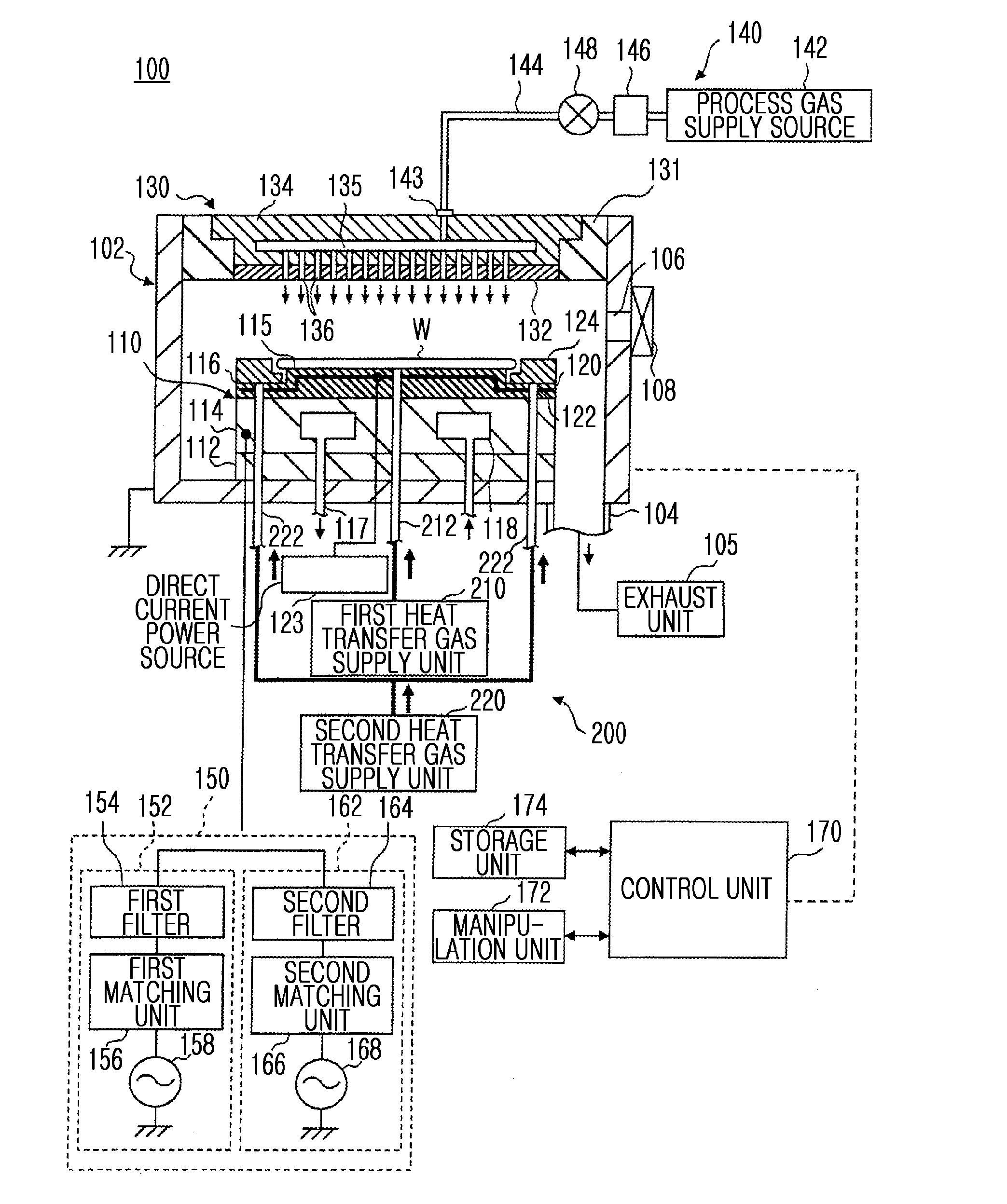
[0048]First, a schematic configuration of a substrate processing apparatus, according to an embodiment of the present invention, will be described with reference to the drawings. Here, the substrate processing apparatus is configured as a parallel plate type plasma processing apparatus. FIG. 1 is a longitudinal-sectional view showing a schematic configuration of a substrate processing apparatus 100, according to the present embodiment.

[0049]The substrate processing apparatus 100 includes, for example, a processing chamber 102 having a cylindrical processing container formed of aluminum of which a surface is anodized (alumite processed). The processing chamber 102 is grounded. A ...


PUM

PropertyMeasurementUnit
current voltageaaaaaaaaaa
radio frequencyaaaaaaaaaa

Abstract

A substrate processing apparatus includes: a holding stage which includes a susceptor having a substrate holding surface on which a wafer is held and a focus ring holding surface on which a focus ring is held; an electrostatic chuck which electrostatically adsorbs a rear surface of the wafer to the substrate holding surface and electrostatically adsorbs a rear surface of the focus ring to the focus ring holding surface; and a heat transfer gas supplying mechanism, wherein the heat transfer gas supplying mechanism independently provides a first heat transfer gas supply unit supplying a first heat transfer gas to the rear surface of the substrate and a second heat transfer gas supply unit supplying a second heat transfer gas to the rear surface of the focus ring.

Description

CROSS-REFERENCE TO RELATED PATENT APPLICATIONS[0001]This application claims the benefit of Japanese Patent Application No. 2010-286075, filed on Dec. 22, 2010, in the Japan Patent Office, and U.S. Patent Application No. 61 / 432,799, filed on Jan. 14, 2011, in the United States Patent and Trademark Office, the disclosures of which are incorporated herein in their entireties by reference.BACKGROUND OF THE INVENTION[0002]1. Field of the Invention[0003]The present invention relates to a substrate processing apparatus and a substrate processing method, which perform a plasma process on a substrate, such as a semiconductor wafer.[0004]2. Description of the Related Art[0005]During a manufacturing process of a semiconductor device, a plasma process, such as etching or film-forming, is repeatedly performed so as to form a minute circuit pattern on a substrate, such as a semiconductor wafer. In the plasma process, for example, plasma is generated by applying a radio frequency voltage between e...

Claims


Application Information

Patent Timeline
Patent Type & Authority Applications(United States)
IPC IPC(8): H01L21/3065
CPCH01J37/32165H01J37/32642H01L21/6831H01L21/67109H01J37/32724H01L21/3065H01L21/67069
Inventor KIKUCHI, EIICHIRONAGAYAMA, NOBUYUKIMIYAI, TAKAHIRO
Owner TOKYO ELECTRON LTD
Why Eureka
Try Eureka