Wireless power transmission system

a power transmission system and wireless technology, applied in the direction of near-field systems using receivers, instruments, inductances, etc., can solve the problems of power loss reduction, inability to insertion the loss of the circulator, etc., and achieve the effect of efficiently transmitting data

Active Publication Date: 2012-06-28
PANASONIC CORP
View PDF1 Cites 85 Cited by
  • Summary
  • Abstract
  • Description
  • Claims
  • Application Information

AI Technical Summary

Benefits of technology

[0043]According to a preferred embodiment of the present invention, while power is being transmitted wirelessly between a power transmitter and a power receiver, the amount of current flowing through the switch of a class E amplifier is monitored. As a result, data can be transmitted efficiently from the power receiver to the power transmitter, and vice versa, with a DC voltage conver

Problems solved by technology

As a result, the power loss can be cut down.
However, whenever a circulator is included in

Method used


Image

  • Wireless power transmission system
  • Wireless power transmission system
  • Wireless power transmission system

Examples


embodiment 1

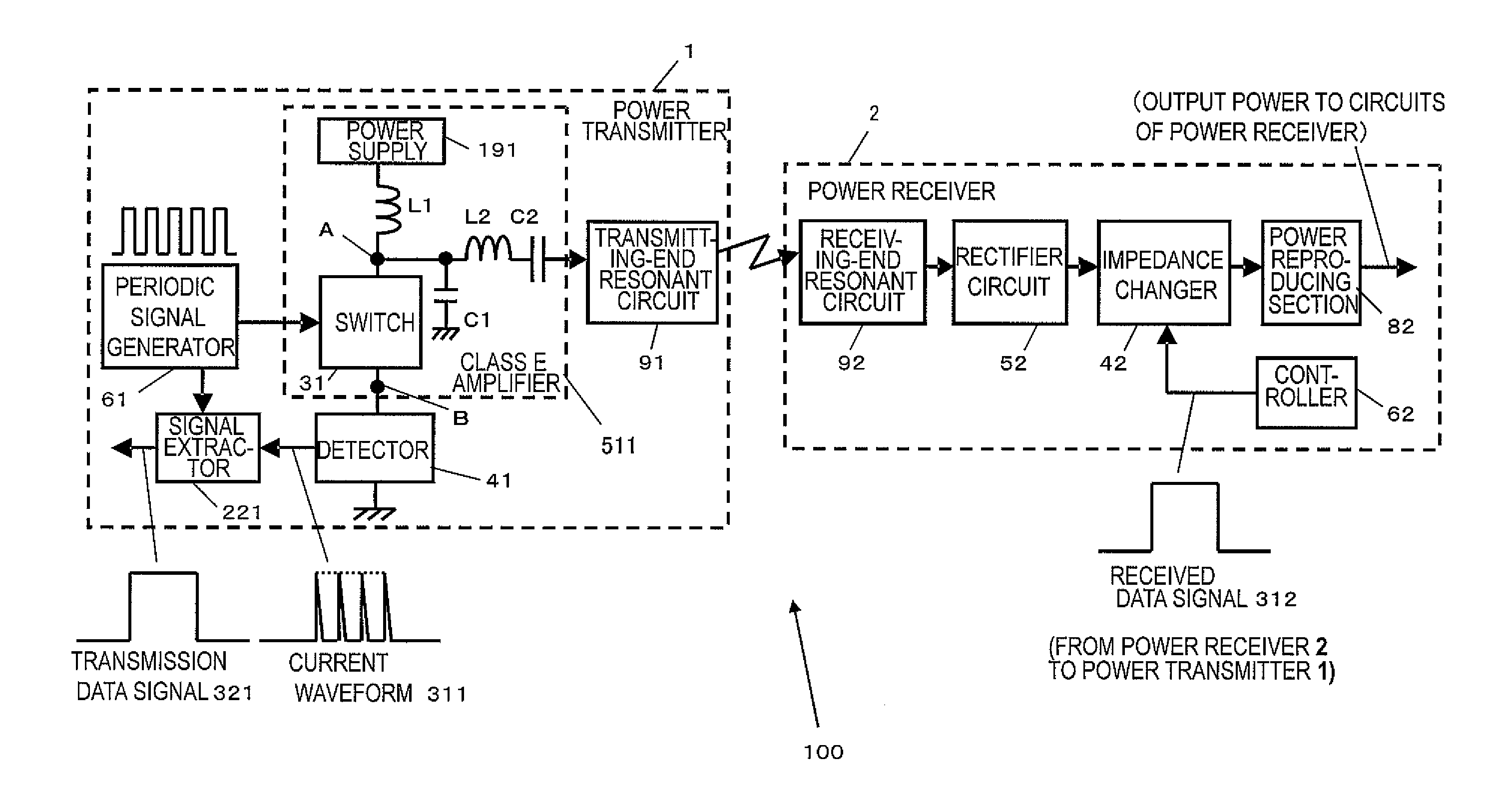
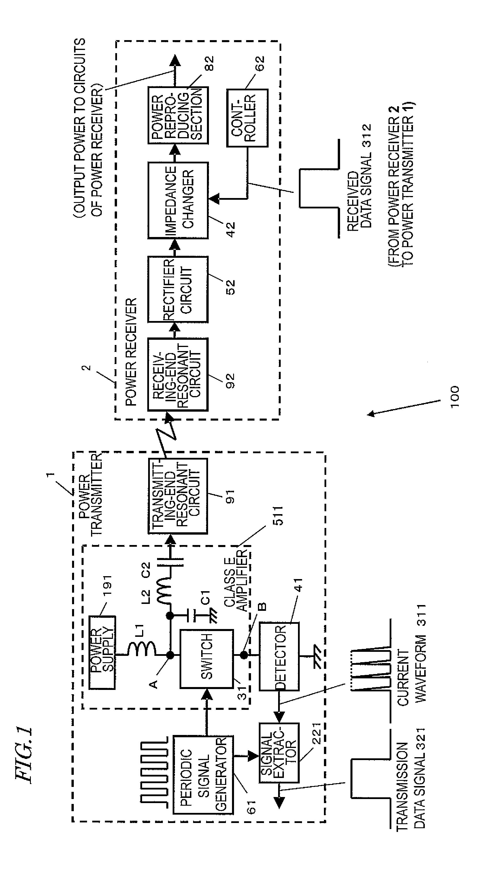
[0057]FIG. 1 is a block diagram illustrating a configuration for a wireless power transmission system 100 as a first specific preferred embodiment of the present invention. This wireless power transmission system 100 includes a power transmitter 1 and a power receiver 2. The power transmitter 1 includes a periodic signal generator 61, a class E amplifier 511, a transmitting-end resonant circuit 91, a detector 41, and a signal extractor 221.

[0058]On the other hand, the power receiver 2 includes a receiving-end resonant circuit 92, a rectifier circuit 52, an impedance changer 42, a power reproducing section 82, and a controller 62.

[0059]The transmitting-end resonant circuit 91 of the power transmitter 1 and the receiving-end resonant circuit 92 of the power receiver 2 together form a resonant circuit that is a combination of a transmission coil, a reception coil, and other elements that are connected to those coils either in parallel or in series. If the transmitting-end resonant circ...

embodiment 2

[0088]FIG. 5 is a block diagram illustrating an exemplary configuration for a wireless power transmission system 110 as a second preferred embodiment of the present invention. In FIG. 5, any component also included in the wireless power transmission system of the first preferred embodiment described above and having substantially the same function as its counterpart is identified by the same reference numeral and a detailed description thereof will be omitted herein.

[0089]In the first preferred embodiment of the present invention described above, data is supposed to be transmitted only in one direction from the power receiver 2 to the power transmitter 1. On the other hand, a wireless power transmission system 110 according to this second preferred embodiment of the present invention can not only transmit power wirelessly from the power transmitter 1 to the power receiver 2 but also transmit data bidirectionally between the power transmitter 1 and the power receiver 2 using a class ...

embodiment 3

[0098]FIG. 7 is a block diagram illustrating an exemplary configuration for a wireless power transmission system 120 as a third preferred embodiment of the present invention. In FIG. 7, any component also included in the wireless power transmission system of the first or second preferred embodiment described above and having substantially the same function as its counterpart is identified by the same reference numeral and a detailed description thereof will be omitted herein.

[0099]The wireless power transmission system of the second preferred embodiment described above is designed to modulate the data to be transmitted from the power transmitter 1 to the power receiver 2 by controlling the power supply 191 of the class E amplifier 511. According to this third preferred embodiment, on the other hand, data is modulated by making a pulse width modulation on the periodic signal, which is a wave to be input to the class E amplifier 511.

[0100]Hereinafter, it will be described with referen...


PUM


Abstract

A wireless power transmission system transmits power wirelessly from a power transmitter to a power receiver. The power transmitter includes a class E amplifier, a transmitting-end resonant circuit, a detector that detects a voltage or current waveform at a predetermined position in the class E amplifier in accordance with the impedance of the transmitting-end resonant circuit as viewed from the class E amplifier, and a signal extractor that extracts a signal according to the waveform. The power receiver includes a receiving-end resonant circuit, a rectifier circuit, a power reproducing section, and an impedance changer connected between the rectifier circuit and the power reproducing section to change its impedance. When the impedance is changed, the detector detects the waveform variation and the signal extractor extracts and outputs a signal corresponding to the waveform detected by the detector.

Description

BACKGROUND OF THE INVENTION[0001]1. Field of the Invention:[0002]The present invention relates to a wireless power transmission system, which includes a power transmitter and a power receiver and which transmits a data signal from the power receiver to the power transmitter, and vice versa, while transmitting power from the power transmitter to the power receiver.[0003]2. Description of the Related Art:[0004]Recently, as cellphones, terrestrial digital TV broadcasting and their related technologies have been further advanced, wireless receivers that receive text data, audio data and telecasts wirelessly as radio waves without using a cable connection have become more and more popular. Currently, electric power is still supplied through a cable to most of those wireless receivers in order to charge its built-in battery to the point that the device is ready to use. However, as those wireless telecommunications technologies have been developing, a lot of people have been attempting now...

Claims


Application Information

Patent Timeline
IPC IPC(8): H02J17/00G06K17/00G06K19/07H04B1/59H04B5/02
CPCH02J2007/0001H02J17/00H02J50/12H02J7/00045H02J50/80H02M7/4815Y02B70/10
Inventor KINOSHITA, KEISUKEKAWAMURA, JUNICHIOKAMURA, SHUTAI
Owner PANASONIC CORP
Why Eureka
Try Eureka