Liquid crystal display

a liquid crystal display and liquid crystal technology, applied in the field of liquid crystal display, can solve the problems of not being able to set input energy to high level, phosphor similarly decreases, and temperature rise in the wavelength conversion portion of light-emitting elements and operation is currently unavoidable, and achieves brighter displayed image and high color reproducibility. ratio

Inactive Publication Date: 2012-06-28
SHARP KK
View PDF0 Cites 25 Cited by
  • Summary
  • Abstract
  • Description
  • Claims
  • Application Information

AI Technical Summary

Benefits of technology

[0051]According to the present invention, a liquid crystal display capable of obtaining a colorful image with high color reproducibility (NTSC ratio) can be provided. In addition, according to the liquid crystal display of the present invention, a brighter displayed image than could be conventionally achieved can be obtained owing to matching between the transmission characteristics of the subpixels of the four colors RGBY of the phosphors and the emission spectrum of the light-emitting device.

Problems solved by technology

While development of structure, material and the like of the entire light-emitting device has been advanced for this purpose, temperature rise in the light-emitting element and the wavelength conversion portion during operation is currently unavoidable.
Luminance of the europium (II)-activated (Sr, Ba)2SiO4 phosphor similarly decreases, which presents a technical problem of not being able to set input energy to high level.
Patent Literature 2, however, does not specifically disclose RG phosphors using blue light as an excitation source.
Patent Literature 3, however, does not disclose color reproducibility (NTSC ratio).

Method used


Image

  • Liquid crystal display
  • Liquid crystal display
  • Liquid crystal display

Examples


example 1

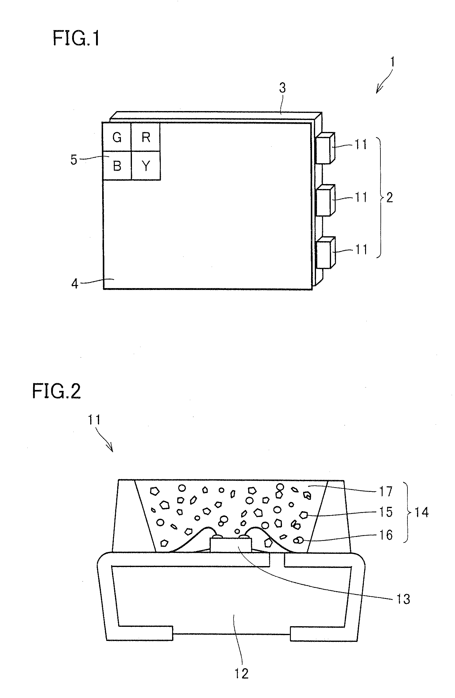
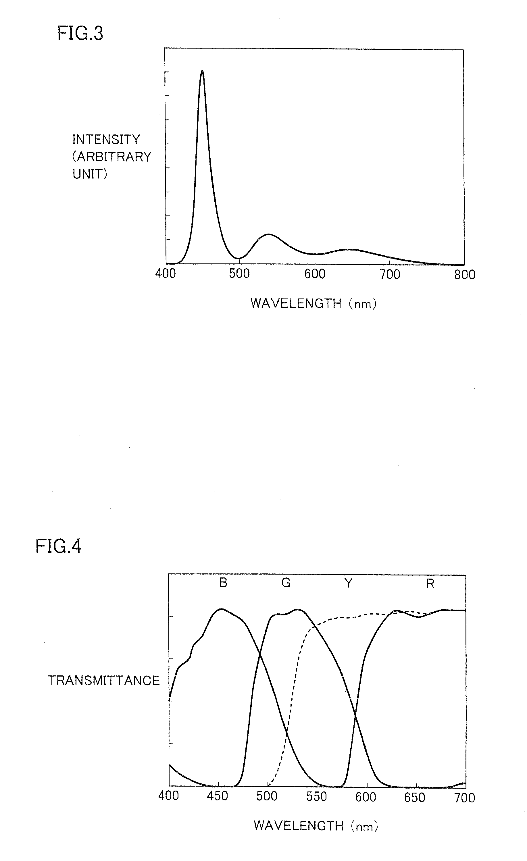
[0103]First, light-emitting device 11 having a structure similar to that shown in FIG. 2 including the light-emitting element mounted on the package and the wavelength conversion portion containing the green phosphor and the red phosphor dispersed in the medium was fabricated. In light-emitting device 11, a gallium nitride (GaN)-based semiconductor having a peak wavelength at 450 nm of blue was used as the light-emitting element, a Eu-activated SiAlON phosphor having a peak wavelength around 540 nm (Eu concentration in crystal: 0.6% by mass, Al concentration in crystal: 2% by mass, oxygen concentration in crystal: 1.1% by mass) was used as the green phosphor, and (Ca0.99Eu0.01)AlSiN3 was used as the red phosphor. A mixture of the green phosphor and the red phosphor in a ratio of 1:0.25 was dispersed into silicone resin which is the medium, to fabricate the wavelength conversion portion. FIG. 3 is a graph showing an emission spectrum of light-emitting device 11 thus obtained, with th...

example 2

[0107]Light-emitting device 11 was fabricated as in Example 1, except for using a Eu-activated β-type SiMON phosphor having a peak wavelength in a range from 520 to 530 nm (Eu concentration in crystal: 0.5% by mass, Al concentration in crystal: 0.6% by mass, oxygen concentration in crystal: 0.3% by mass) as the green phosphor, using (Ca0.99Eu0.01)AlSiN3 as the red phosphor, and mixing the green phosphor and the red phosphor in a ratio of 1:0.33. FIG. 8 is a graph showing an emission spectrum of the light-emitting device obtained in Example 2, with the axis of ordinate representing intensity (arbitrary unit), and the axis of abscissa representing wavelength (nm). As shown in FIG. 8, the light-emitting device obtained in Example 2 has spectral characteristics adjusted in accordance with transmission characteristics of a liquid crystal display to be described below. The liquid crystal display was fabricated as in Example 1 by using the light-emitting device thus obtained as a backlight...

example 3

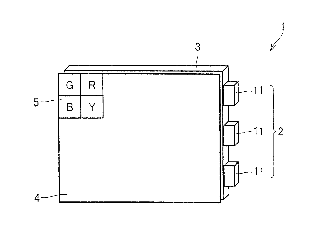
[0113]FIG. 11 is a configuration diagram of a liquid crystal television 80 incorporating the light-emitting device similar to that used in Example 1 except that the device is of a top emission type rather than of a side emission type as a backlight light source, and including a liquid crystal display having subpixels of red (R), green (G), blue (B) and yellow (Y), and circuits for driving the liquid crystal display. Here, the light-emitting devices similar to that used in Example 1 except that the devices are of a top emission type rather than of a side emission type were arranged in a matrix on a backside of a liquid crystal display panel, to fabricate a liquid crystal television having a screen size of 46 inches using a liquid crystal display 81 which is a liquid crystal panel of an area active type (local dimming type) for emitting LED light from the backside. In liquid crystal display 81, each pixel 82 includes subpixels of red (R), green (G), blue (B) and yellow (Y).

[0114]Liqui...


PUM

PropertyMeasurementUnit
emission peak wavelengthaaaaaaaaaa

Abstract

A liquid crystal display including a backlight and a filter, the backlight including a light-emitting device having a light-emitting element emitting blue light, and a green phosphor and a red phosphor absorbing a part of primary light emitted from the light-emitting element and emitting first secondary light and second secondary light, respectively, the green phosphor being a β-type SiAlON phosphor containing Eu and Al dissolved in a crystal of a nitride or an oxynitride having a β-type Si3N4 crystal structure, and the filter including filters for colors of red (R), green (G), blue (B) and yellow (Y), respectively, arranged in a plane for subpixels provided in each pixel of the liquid crystal display, which attains excellent color reproducibility (NTSC ratio) and high luminance, can be provided.

Description

TECHNICAL FIELD[0001]The present invention relates to a liquid crystal display (LCD) using a light-emitting device including a light-emitting element emitting primary light and a wavelength conversion portion absorbing the primary light and emitting secondary light as a backlight.BACKGROUND ART[0002]A light-emitting device including combination of a semiconductor light-emitting element and a phosphor has attracted attention as the next-generation light-emitting device expected to achieve low power consumption, small size, high luminance, and color reproduction of a broader range, and research and development of such light-emitting device has actively been conducted.[0003]Light in a range from ultraviolet to blue having a long wavelength, that is, a wavelength from 380 to 480 nm, is normally employed as primary light emitted from a light-emitting element. There have also been proposed wavelength conversion portions using various types of phosphors suitable for this application. In ad...

Claims


Application Information

Patent Timeline
Patent Type & Authority Applications(United States)
IPC IPC(8): G02F1/1335G02F1/13357
CPCC09K11/7734G02F2001/133614G02F1/133603G02F1/133514G02F1/133615C04B2235/3224G02F1/133609C04B2235/767C04B35/597H01L2224/32245H01L2224/48091H01L2224/48247H01L2224/48257H01L2224/48465H01L2224/73265G02F1/133614C09K11/77348H01L2924/00014H01L2924/00012H01L2924/00
Inventor TAKAHASHI, KOHSEIWATANABE, MASANORIHANAMOTO, TETSUYAMASUDA, MASATSUGUTERASHIMA, KENJI
Owner SHARP KK
Why Eureka
Try Eureka