System for mitral valve repair and replacement

a technology for mitral valves and systems, applied in the field of medical devices, to achieve the effect of increasing the flexibility of devices, increasing the flexibility of assemblies, and increasing flexibility

Active Publication Date: 2012-06-28
TWELVE
View PDF26 Cites 238 Cited by
  • Summary
  • Abstract
  • Description
  • Claims
  • Application Information

AI Technical Summary

Benefits of technology

[0016]In yet another variation, one or more of the arm members themselves may be formed of multiple links or segments which increase the flexibility of the device. The arm members formed of the links or segments may provide for increased flexibility of the assemblies when placed against the leaflets. Having the increased flexibility may allow for the interventional device to more closely conform to a particular anatomy of a valve and may further provide for enhanced support of the valve.
[0017]Additionally and / or alternatively, one or all of the arm members may have rounded or curved edges to facilitate delivery of the device through the catheter as well as to reduce any potential wear against the internal catheter surface. For example, if a delivery catheter having a 6 mm internal diameter, each respective arm member may have a cross sectional width, e.g., of about 5 mm and a height, e.g., of about 2 mm. Having the curved edges may allow for the translation of the device through the catheter lumen without wearing along the lumen surfaces. Moreover, the curved surfaces and edges of each arm member may also reduce any potential wear on the contacted mitral leaflets as well.

Problems solved by technology

Moreover, one or more interventional devices may be deployed in or near one or both valve commissures with the deployed arm members compressing the leaflets therebetween, stabilizing a portion of the valve leaflets while allowing the remainder of the leaflet(s) to move in an uninhibited fashion.

Method used


Image

  • System for mitral valve repair and replacement
  • System for mitral valve repair and replacement
  • System for mitral valve repair and replacement

Examples


Embodiment Construction

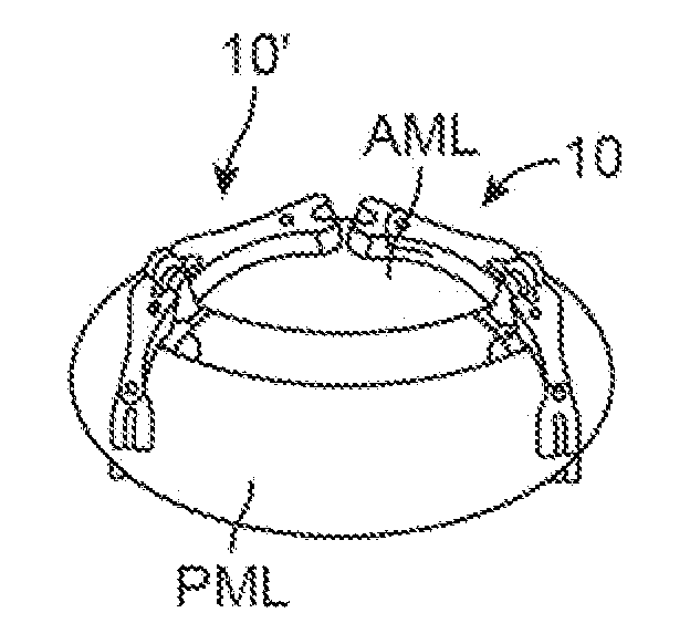
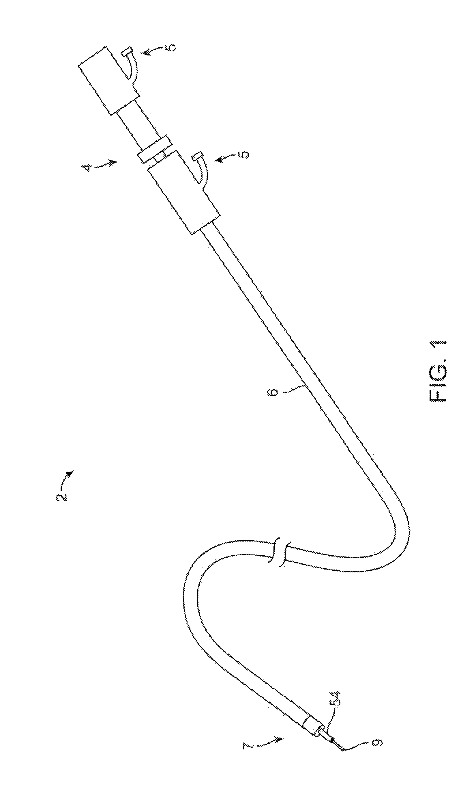
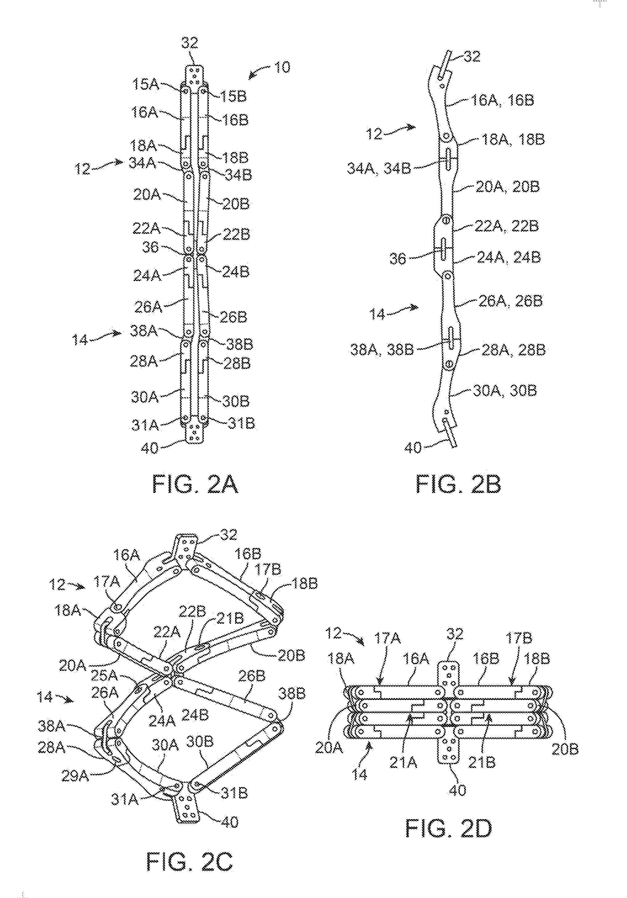
[0092]In repairing and / or replacing a defective heart valve, such as a mitral valve, an interventional device may be advanced intravascularly into the heart of a patient and deployed upon or along the mitral valve to affect the abnormal functioning of the valve leaflets. The interventional device may also facilitate the placement or anchoring of a prosthetic mitral valve implant in an efficient manner. In one variation, the interventional device may generally comprise a distal stabilizing structure 14 pivotably and / or rotatably coupled to a proximal stabilizing structure 12. The distal stabilizing structure 14 may be advanced past the catheter opening, through the mitral annulus, and reconfigured from a low-profile, axially-elongated delivery configuration, as shown in FIG. 2A, to a laterally-elongated deployed configuration, as shown in FIG. 2C. Deployment of the distal stabilizing structure may result from the urging of a biasing element, such as a torsion spring, and / or the tensi...


PUM


Abstract

Systems for mitral valve repair are disclosed where one or more mitral valve interventional devices may be advanced intravascularly into the heart of a patient and deployed upon or along the mitral valve to stabilize the valve leaflets. The interventional device may also facilitate the placement or anchoring of a prosthetic mitral valve implant. The interventional device may generally comprise a distal set of arms pivotably and/or rotating coupled to a proximal set of arms which are also pivotably and/or rotating coupled. The distal set of arms may be advanced past the catheter opening to a subannular position (e.g., below the mitral valve) and reconfigured from a low-profile delivery configuration to a deployed securement configuration. The proximal arm members may then be deployed such that the distal and proximal arm members may grip the leaflets between the two sets of arms to stabilize the leaflets.

Description

CROSS-REFERENCE TO RELATED APPLICATIONS[0001]This application claims the benefit of priority to U.S. Prov. Pat. App. Nos. 61 / 460,041 filed Dec. 23, 2010 and 61 / 499,630 filed Jun. 21, 2011, each of which is incorporated herein by reference in its entirety.FIELD OF THE INVENTION[0002]The present invention relates generally to medical devices used for the repair of dysfunctional heart valves. More particularly, the present invention relates to devices and methods used for the repair and / or replacement of the mitral valve.BACKGROUND OF THE INVENTION[0003]Conditions affecting the proper functioning of the mitral valve include, for example, mitral valve regurgitation, mitral valve prolapse and mitral valve stenosis. Mitral valve regurgitation is a disorder of the heart in which the leaflets of the mitral valve fail to coapt into apposition at peak contraction pressures, resulting in abnormal leaking of blood from the left ventricle into the left atrium. There are a number of structural fa...

Claims


Application Information

Patent Timeline
Patent Type & Authority Applications(United States)
IPC IPC(8): A61F2/24
CPCA61F2/2418A61F2/243A61F2/2445A61F2/2466A61F2230/0008A61F2250/0004A61F2250/0008A61F2250/006A61F2220/0016A61F2250/0003A61F2220/0075A61F2/2454
Inventor GIFFORD, III, HANSON S.FANN, JAMES I.MORRISS, JOHNDEEM, MARKGRAINGER, JEFFRY J.
Owner TWELVE
Why Eureka
Try Eureka