The Concorde, which has been the only commercial supersonic transport (SST) aircraft, has been plagued with problems of economic efficiency and environmental acceptability due to engine
noise and
sonic boom.
The former is an aerodynamic
physical constant, and so artificial control is difficult.
The other is
instability arising from velocity components within the boundary layer induced by a pressure gradient in the direction perpendicular to the direction of flow occurring on a three-dimensional
swept wing.
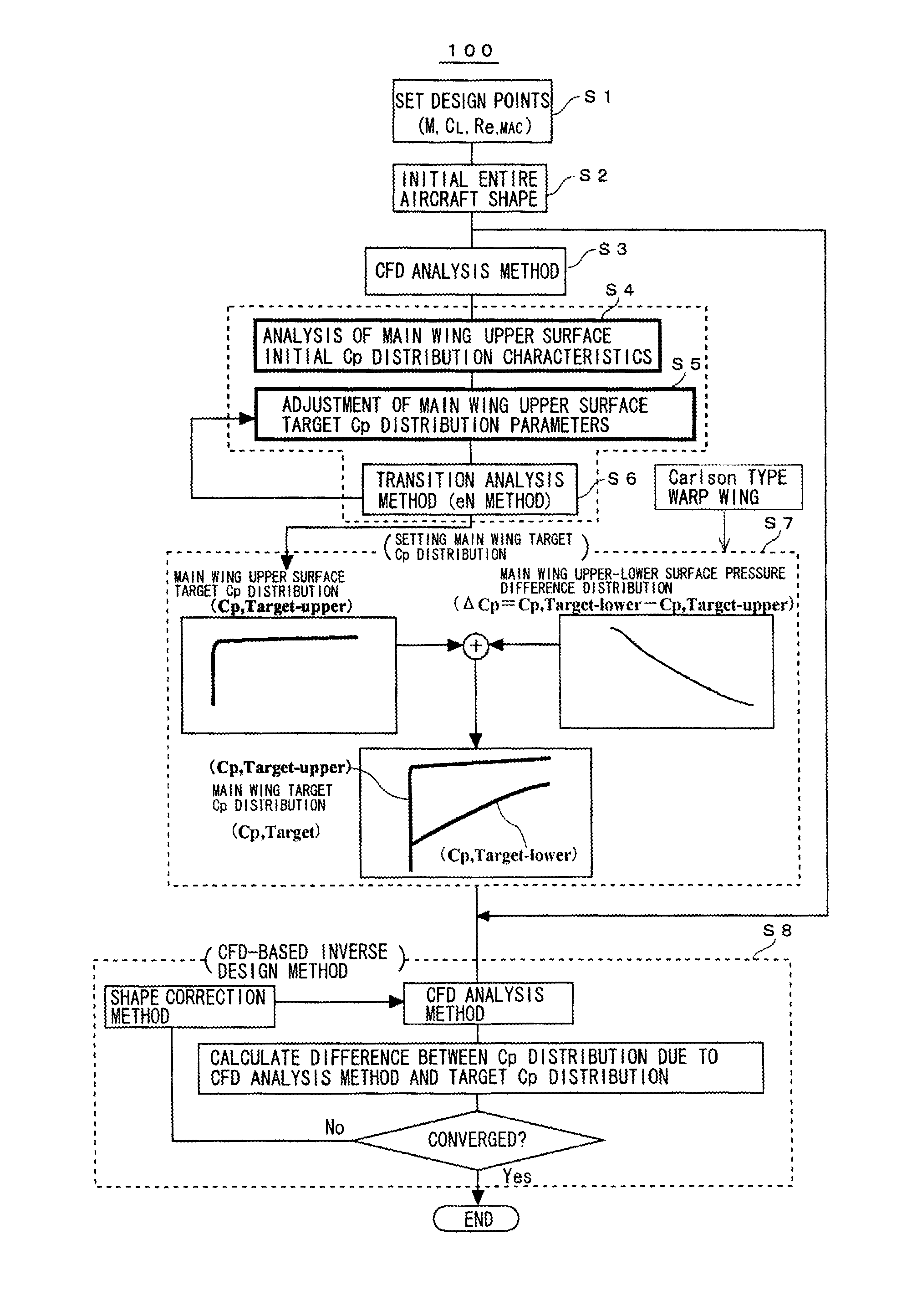
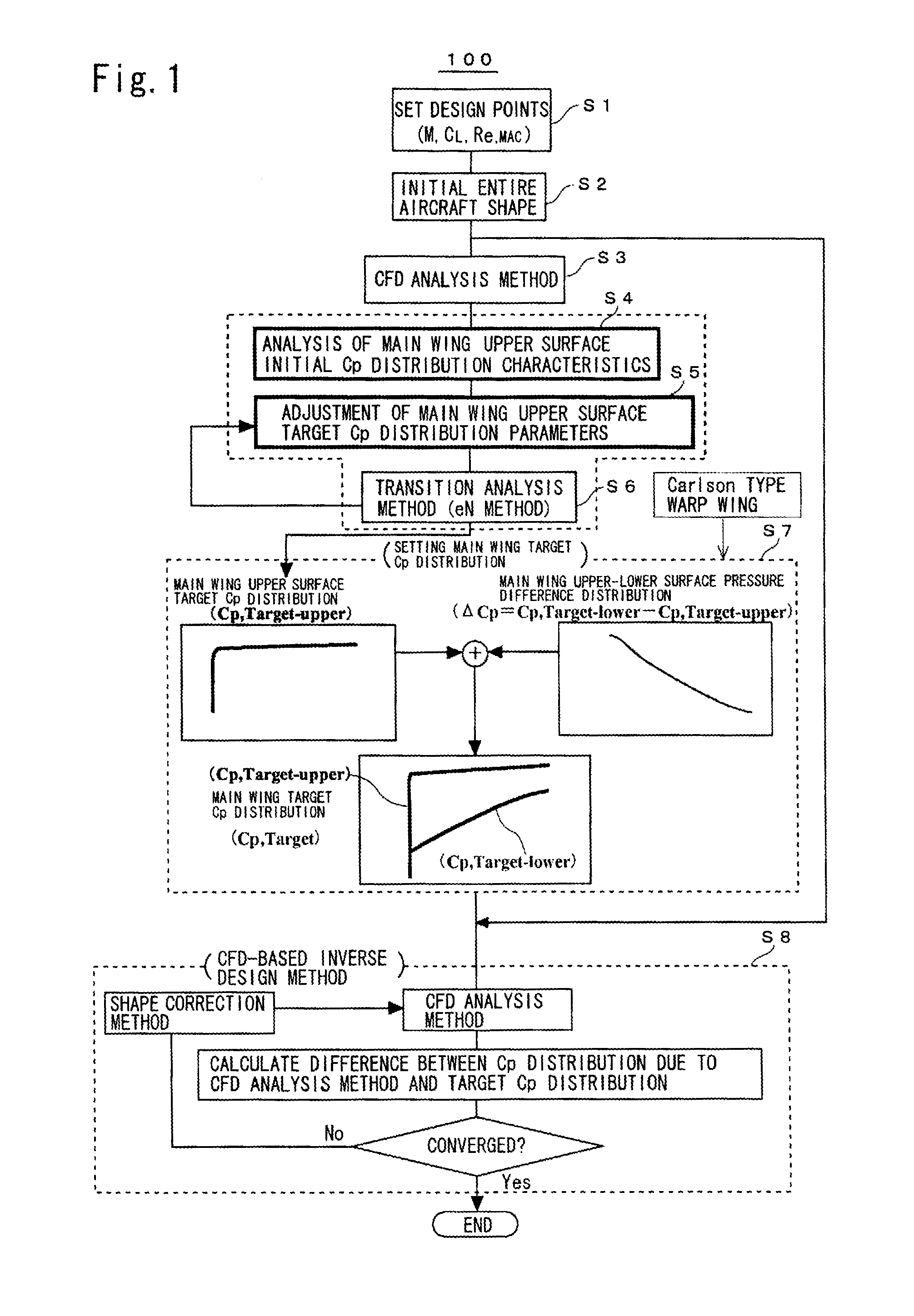
Further, creation of the target Cp distribution (Cp, target-upper) of this main wing upper surface requires an excessive amount of effort, since the pressure distribution must be set over the entire main wing surface along the wing chordwise direction from the wing
leading edge to the wing
trailing edge at each spanwise
station.
Here, “qualitatively” means that, in the case of wind tunnel tests, because disturbances necessarily occur in the mechanism of the wind tunnel generating a supersonic
airflow, the
airflow from upstream already includes significant small turbulence, and this is combined with
instability of the boundary layer so that there exists a physical mechanism promoting transition, and insofar as it is generally difficult to eliminate this influence (in rare and specific wind tunnel conditions, it has been possible to greatly suppress this wind tunnel
airflow turbulence, but complete
elimination has not been possible), it is thought that the effect of some airflow turbulence is exerted on the transition phenomenon.
However, in these experiments, insofar as a scaled
airplane of total length 11.5 m was used, the Reynolds number is also 11% of that of the assumed large-scale SST, and the above-described natural laminar flow wing design method developed in the NEXST project has problems from the standpoint of establishing techniques for application to actual aircraft design; it became clear that there is a need for considerable improvement of the target pressure distribution shape found in the design of NEXST-1
airplane (see Y. Ueda and K. Yoshida, “Numerical Study on Optimum Pressure Distribution for Supersonic Natural Laminar Flow Wing Design”, Proc.
In particular, for high Reynolds numbers corresponding to actual aircraft, C-F instabilities are extremely strong, and in the target pressure distribution for the main wing upper surface found in the NEXST-1 actual
airplane design as well, it was subsequently found that an adequate effect was not exhibited.
The main reason for this was errors arising from the precision of the model in the transition
analysis method used at that time.
When this
leading edge has a characteristic cross-sectional shape with a sharp thin distribution, the pressure gradient in the flow direction reliably decreases monotonically, and so there is the
advantage of an accelerating gradient which is effective for suppressing T-S
instability; but because with the low
aspect ratio the sweep angle is small, in the above-described range of approximately 10 to 20°, the lift-dependent drag increases, and it is thought that achievement of reductions in both friction drag and pressure drag is difficult.
The effect of
transition point delay through this technique has been visually confirmed in flight experiments with this main wing shape perpendicularly mounted to the lower
fuselage of an F-15 fighter (however, the wing itself was equivalent to a
scale model); an advanced
engineering level with respect to confirmation of natural laminarization through an actual flight
airframe is evident, but considering that a
scale model was used (the Reynolds number did not correspond to that of an actual aircraft) and that simultaneous reduction of pressure drag was not attempted, this research is regarded as quite incomplete with respect to application to actual aircraft design.

