Method and apparatus for manufacturing vitreous silica crucible

Inactive Publication Date: 2012-07-05
SUMCO CORP
View PDF31 Cites 3 Cited by
  • Summary
  • Abstract
  • Description
  • Claims
  • Application Information

AI Technical Summary

Benefits of technology

[0026]According to the apparatus, the temperature near the surface of the silica powder layer which is fused in a stringent environment over 2000 deg. C. can be measured precisely in real time. Thus, the fused state required for manufacturing a vitreous silica crucible can be detected precisely and easily. The fused state can be precisely fed back to the manufacturing conditions, and thus more precise control of the manufacturing conditions is possible.
[0050]According to the present invention, it is possible to measure the temperature of vitreous silica during fusing in real time, and thus it is possible to prevent the problem that the thickness at the corner portion becomes too thick when the fusing temperature is too high or the problem that temperature change changes the parameters of the inner surface property so as to adversely affects pulling of a silicon single crystal. Therefore, according to the present invention, it is possible to manufacturing a vitreous silica crucible having a preferable property.

Problems solved by technology

Therefore, it is not possible to measure such high temperature during operation in the state of the art.
Furthermore, it is also not possible to measure the surface temperature of an object heated and fused near arc flame because the measurement condition is very severe.
Therefore, it is difficult to control the temperature during manufacturing a vitreous silica crucible.
Furthermore, the amount of heat generation is controlled by controlling the voltage value in the conventional controlling method, but the voltage value is not stable and thus fluctuates during arc generation.
Therefore, according to the control based on the voltage value, it is difficult to match the movement of the electrodes with the change of the voltage value, and thus it is difficult to continue thermally stable arc generation.

Method used


Image

  • Method and apparatus for manufacturing vitreous silica crucible
  • Method and apparatus for manufacturing vitreous silica crucible
  • Method and apparatus for manufacturing vitreous silica crucible

Examples


example

[0135]Hereinafter, the present invention will be explained in more detail with reference to the examples. The present invention is not limited by these examples.

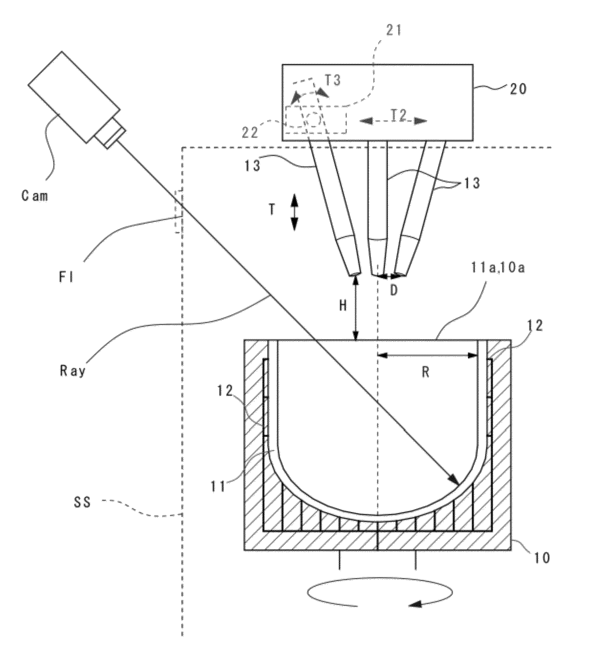
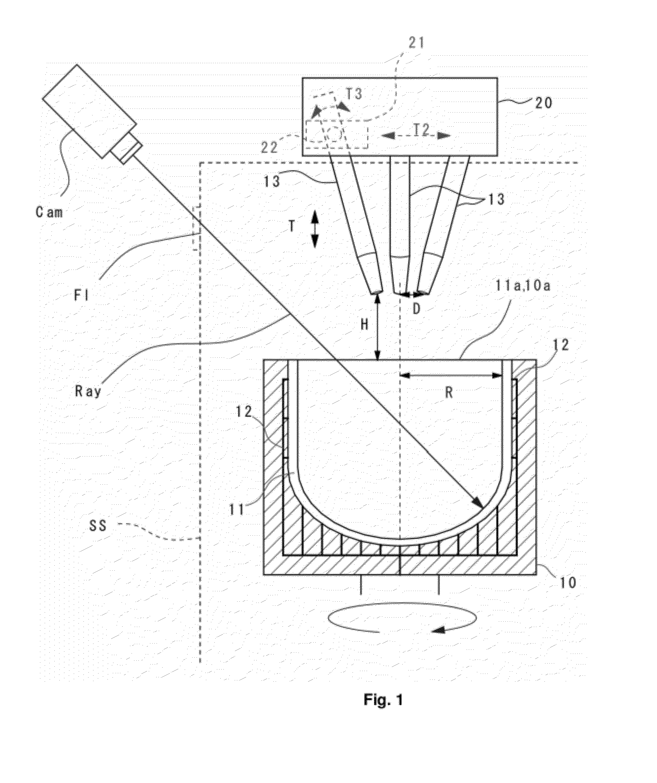
[0136]A vitreous silica crucible having a diameter of 610 mm (24 inches) was manufactured. Nine samples were manufactured according to the conditions of Examples 1 to 9 of Table 1, and two samples were manufactured according to the conditions of Comparative Examples 1 to 2. In the manufacturing, the height position H of the electrode tips 13a was subjected to time-course change as shown in FIG. 10 by the electrode position setting unit 20 shown in FIG. 1. The height position was H1 from time t0 to t1, and the height position was H2 from time t2 to t3 (H1>H2).

[0137]While manufacturing, the temperature at the position R-W shown in FIG. 4 was measured during arc fusing by use of a radiation thermometer, and the temperature control is carried out by the fine adjustment of the height position H and the supplied power so as to adj...


PUM

PropertyMeasurementUnit
Lengthaaaaaaaaaa
Temperatureaaaaaaaaaa

Abstract

Accurate temperature measurement during manufacturing a vitreous silica crucible is enabled. The present invention provides an apparatus for manufacturing a vitreous silica crucible including: a mold for forming a silica powder layer by supplying silica powder therein; an arc discharge unit having carbon electrodes and a power supply unit and for heating and fusing the silica powder layer by arc discharge; and a temperature measurement unit for measuring temperature of a fused portion in the mold, wherein the temperature measurement unit is an radiation thermometer for measuring temperature by detecting radiation energy of a wavelength of 4.8 to 5.2 μm.

Description

CROSS-REFERENCE TO RELATED APPLICATION[0001]This application is related to Japanese Patent Application No. 2010-294630 filed on Dec. 31, 2010, whose priority is claimed and the disclosure of which is incorporated by reference in its entirety.BACKGROUND OF THE INVENTION[0002]1. Field of the Invention[0003]The present invention relates to a method and apparatus for manufacturing a vitreous silica crucible, and in particular relates to a technique suitable for controlling the inner surface property of a vitreous silica crucible used for pulling a silicon single crystal.[0004]2. Description of the Related Art[0005]A silicon single crystal has been manufactured by the Czochralski method (the CZ method) using a vitreous silica crucible. In this method, polycrystalline silicon raw material is melted and retained in the vitreous silica crucible, a seed crystal of silicon single crystal is dipped into the silicon melt, and the seed crystal is gradually pulled while rotating it, to produce a ...

Claims


Application Information

Patent Timeline
IPC IPC(8): C03B20/00C03B19/09
CPCG01J5/0862G01J5/0022C03B19/095G01J5/0037C03B2201/02Y02P40/57G01J5/0802C03B20/00C30B15/10C30B29/06
Inventor SUDO, TOSHIAKISUZUKI, ERIKO
Owner SUMCO CORP
Why Eureka
Try Eureka