
Composition and method for in-system priming microfluidic devices

a microfluidic device and in-system technology, applied in water supply installation, transportation and packaging, laboratory glassware, etc., can solve the problems of reducing thermal control, affecting the testing of chemical or biological samples using the microfluidic chip, and uncontrollable flow of liquid within the chip, so as to reduce the likelihood of inaccurate test results and reduce the time required for priming

Inactive Publication Date: 2012-07-05
CANON US LIFE SCIENCES INC
View PDF2 Cites 3 Cited by
  • Summary
  • Abstract
  • Description
  • Claims
  • Application Information

AI Technical Summary

Benefits of technology

[0010]This invention relates to compositions and methods for in-system priming of microfluidic devices that reduce the likelihood of inaccurate test results and reduces the time required for priming.
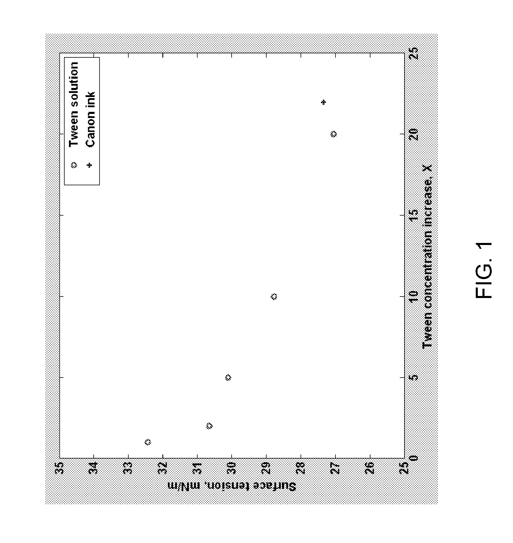
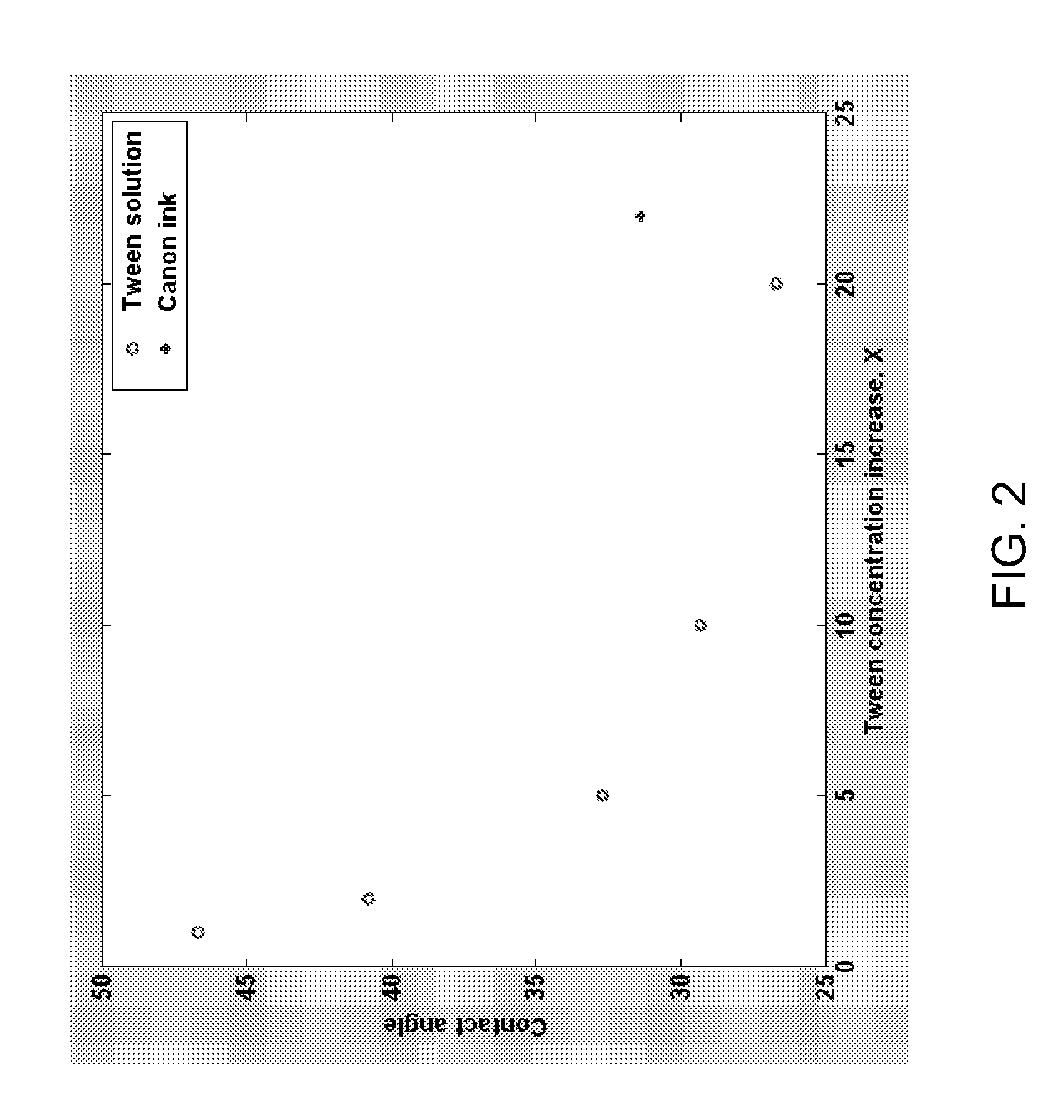
[0011]In one aspect, the invention provides a priming solution for dry priming microfluidic chips. The priming solution has high wettability, is PCR compatible and enables higher PCR efficiency. In one embodiment, the priming solution comprises a conventional 1×PCR buffer with an increased concentration of surfactant. The surfactant in the PCR buffer is increased by adding a surfactant to the PCR buffer or by increasing the concentration of the surfactant in the PCR buffer. The priming solution may also contain a dye to follow the in-system priming of a microfluidic device.
[0012]In one embodiment, the priming solution is a 1×PCR buffer in which the concentration of surfactant in the 1×PCR buffer ranges from a factor of about 5 to a factor of about 150 of the CMC for the particular surfactant(s) present in the 1× PCR buffer, preferably from a factor of about 12 to a factor of about 150, more preferably from factor of about 15 to a factor of about 135, even more preferably from a factor of about 30 to a factor of about 120. In another embodiment, priming solutions with a surfactant concentration in the lower range exhibit better drop formation. In this embodiment, the concentration of surfactant in the 1×PCR buffer ranges from a factor of about 5 to a factor of about 45 of the CMC for the particular surfactant(s) present in the 1×PCR buffer, preferably from a factor of about 12 to a factor of about 45 more preferably from factor of about 15 to a factor of about 30.
[0013]In one embodiment, the priming solution is a 1×PCR buffer in which the surfactant is Tween® 20 and the concentration is in the range of about 0.05% to about 1.0%, preferably about 0.8% to about 1.0%, more preferably from about 0.1% to about 0.9%, even more preferably from about 0.2% to about 0.8%. In another embodiment, priming solutions with a surfactant concentration in the lower range, e.g., from about 0.05% to about 0.3%, preferably from about 0.08% to about 0.3%, more preferably from about 0.1% to about 0.2%, exhibit better drop formation.
[0015]In accordance with another embodiment of the invention, the method comprises the steps of treating the microfluidic devices or microfluidic chips with plasma, applying a priming solution to a microfluidic device and applying an external pressure to flow or move the priming solution along the microchannels and through the joint of different microfluidic chips that may be used together in a microfluidic device. The plasma treatment increases the hydrophilicity of the microchannel surfaces. In one embodiment, the method further comprises the step of allowing capillary pressure to flow or move the priming solution along the microfluidic channels of the microfluidic device before the external pressure is applied. In some embodiments, the priming solution is a PCR buffer. In other embodiments, the priming solution is a PCR buffer having an increased surfactant concentration as described herein.

Problems solved by technology

The presence of air bubbles in mixtures in a chip may adversely affect the testing of chemical or biological samples using the microfluidic chip.
For example, air bubbles may cause the flow of liquid within the chip to be uncontrollable.
Air bubbles may also, in some systems, cause reduced thermal control.
The priming of a microfluidic chip, if performed inaccurately or incorrectly, may cause an analysis performed using the microfluidic chip to be erroneous and, hence, unreliable.

Method used


Image

  • Composition and method for in-system priming microfluidic devices
  • Composition and method for in-system priming microfluidic devices
  • Composition and method for in-system priming microfluidic devices

Examples


Embodiment Construction

[0022]The present invention has several embodiments and relies on patents, patent applications and other references for details known to those of the art. Therefore, when a patent, patent application, or other reference is cited or repeated herein, it should be understood that it is incorporated by reference in its entirety for all purposes as well as for the proposition that is recited.

[0023]The practice of the present invention may employ, unless otherwise indicated, conventional techniques and descriptions of organic chemistry, polymer technology, molecular biology (including recombinant techniques), cell biology, biochemistry, and immunology, which are within the skill of the art. Such conventional techniques include polymer array synthesis, hybridization, ligation, and detection of hybridization using a label. Specific illustrations of suitable techniques can be had by reference to the example herein below. However, other equivalent conventional procedures can, of course, also ...


PUM

PropertyMeasurementUnit
diameteraaaaaaaaaa
pressureaaaaaaaaaa
pressureaaaaaaaaaa

Abstract

The present invention relates to compositions and methods for in-system priming of microfluidic devices. Aspects of the present invention relate to compositions and methods for in-system priming of microfluidic devices utilizing a priming solution comprising adding and / or increasing concentrations of surfactant in a buffer solution.

Description

CROSS-REFERENCE TO RELATED APPLICATION[0001]The present application claims the benefit of priority to U.S. provisional patent application Ser. No. 61 / 378,543, filed on Aug. 31, 2010, the entire disclosure of which is incorporated herein by reference.BACKGROUND[0002]1. Field of the Invention[0003]This invention relates to compositions and methods for in-system priming of microfluidic devices. More specifically, aspects of the present invention relate to compositions and methods for in-system priming of microfluidic devices utilizing a priming solution comprising adding and / or increasing concentrations of surfactant in a buffer solution.[0004]2. Discussion of Related Art[0005]The detection of nucleic acids is central to medicine, forensic science, industrial processing, crop and animal breeding, and many other fields. The ability to detect disease conditions (e.g., cancer), infectious organisms (e.g., HIV), genetic lineage, genetic markers, and the like, is ubiquitous technology for d...

Claims


Application Information

Patent Timeline
Patent Type & Authority Applications(United States)
IPC IPC(8): F17D1/00C12Q1/68
CPCB01L3/50273B01L2200/10B01L2200/146B01L2400/0487B01L2300/0816B01L2300/18B01L2200/147Y10T137/0318C12Q1/6806
Inventor WANG, YING-XINCOURSEY, JOHNATHAN S.SCHMIDT, JASONHASSON, KENTON C.
Owner CANON US LIFE SCIENCES INC
Learn More