Circuit and method for reducing input leakage in chopped amplifier during overload conditions

a technology of amplifier and input leakage, which is applied in the direction of amplifiers, amplifiers with semiconductor devices/discharge tubes, electrical devices, etc., can solve the problems of affecting the reliable detection of the disconnection of the electrode from the human body, affecting the reliability of the detection of the disconnection of the electrode, and the foregoing technique of preventing amplifier overload/saturation conditions by reducing the amplifier gain

Active Publication Date: 2012-07-05
DURACELL U S OPERATIONS +1
View PDF1 Cites 3 Cited by
  • Summary
  • Abstract
  • Description
  • Claims
  • Application Information

AI Technical Summary

Benefits of technology

[0017]It is an object of the invention to provide a chopper-stabilized amplifier and method

Problems solved by technology

However, when ΔVIN exceeds the dynamic input voltage range limit of chopper-stabilized INA 1, its output becomes “saturated”.
For example, there are medical safety specifications which do not permit more than a certain amount of current, e.g., 1 microampere, to flow into or out of the human body.
If during saturation ILEAKAGE increases to a value larger than the current injected into or out of the human body, it may prevent the input signal from moving sufficiently close to the supply voltage, thereby interfering with reliable detection of the

Method used


Image

  • Circuit and method for reducing input leakage in chopped amplifier during overload conditions
  • Circuit and method for reducing input leakage in chopped amplifier during overload conditions
  • Circuit and method for reducing input leakage in chopped amplifier during overload conditions

Examples


Embodiment Construction

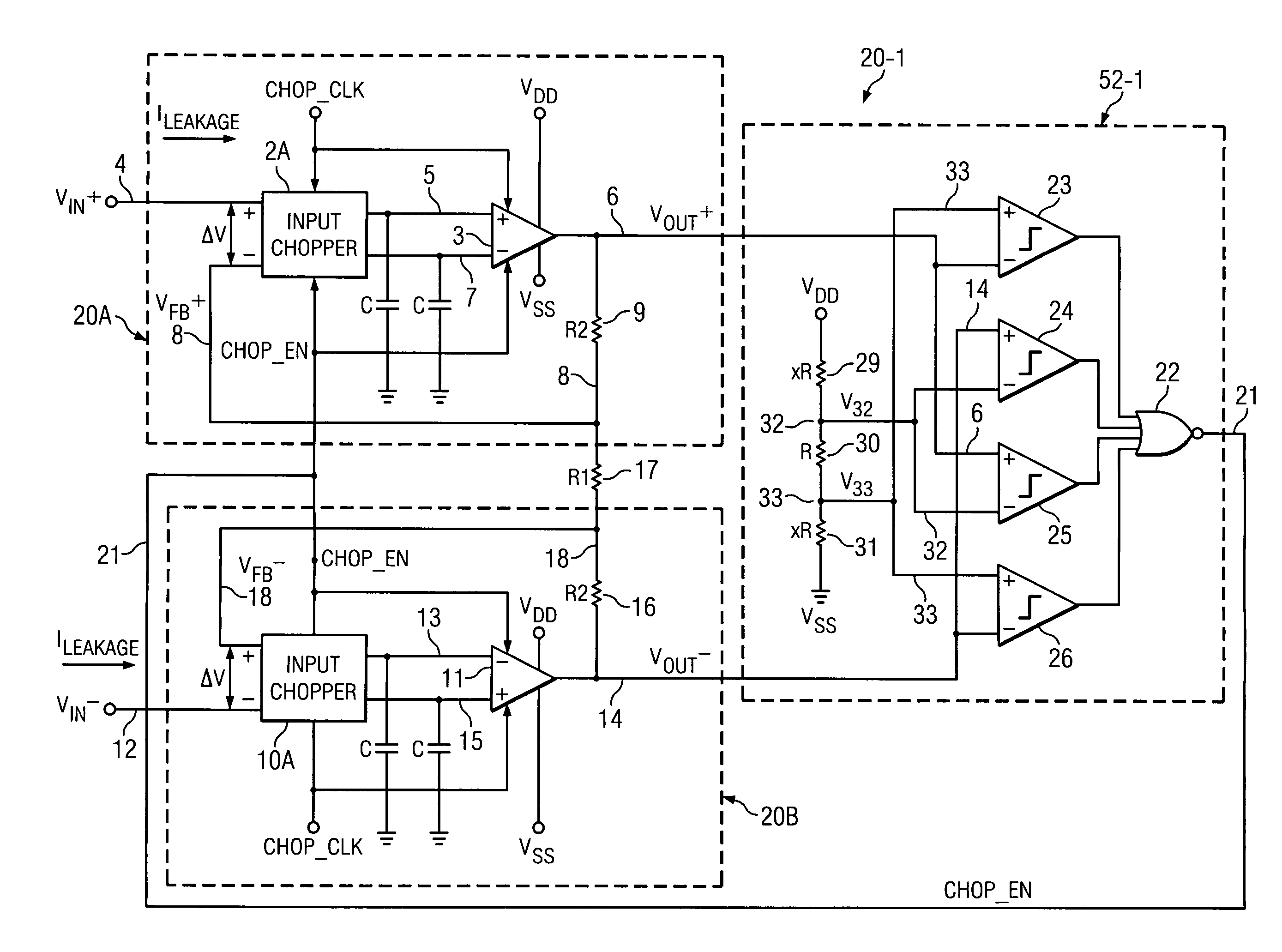
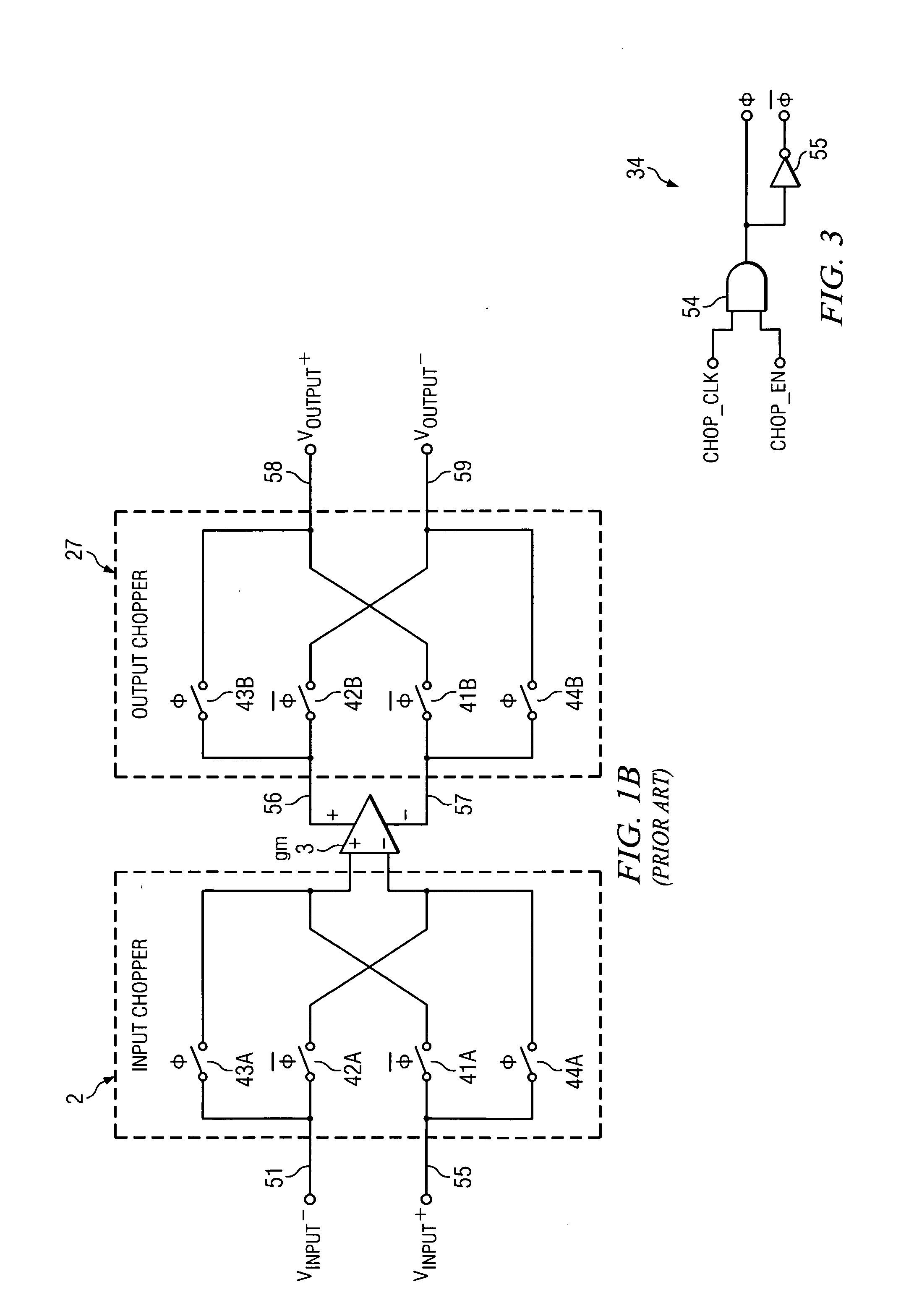
[0044]Referring to FIG. 2, chopper-stabilized instrumentation amplifier (INA) 20-1 includes an “upper” chopper-stabilized amplifier 20A including input chopper 2A, amplifier 3, and an output chopper 27A. INA 20-1 also includes a “lower” chopper-stabilized amplifier 20B including input chopper 10A, amplifier 11, and output chopper 28A. Amplifiers 3 and 11 each include an output chopper circuit that may be essentially the same as output chopper 27 in previously described FIG. 1B. Input chopper 2A also may be implemented essentially the same as in input chopper 2 in FIG. 1B, and depending on the particular application requirements, the combination of input chopper 2 and amplifier 3 in FIG. 2 may be the same as the input chopper, folded-cascode amplifier, and output chopper shown in FIG. 4 of the previously mentioned article “A Low Noise, Low Residual Offset, Chopped Amplifier for Mixed Level Applications” by M. Sanduleanu, A. van Tuigal, R. Wasasenaar, and H. Walling a. That is, input ...


PUM


Abstract

A chopper-stabilized amplifier (20A) includes an amplifier (3), an input chopper (2A) having a first input (4) receiving an input signal (VIN+), an output (5) coupled to a first input of the amplifier, and a feedback resistor (9) coupled to an output (6) of the amplifier to couple a feedback signal (VFB+) to a second input of the amplifier (3). The input chopper operates in response to a chopping clock (CHOP_CLK). If the amplifier (3) is unacceptably close to a saturation condition, the chopping clock (CHOP_CLK) is disabled to reduce input leakage current (ILEAKAGE) of the chopper-stabilized amplifier.

Description

BACKGROUND OF THE INVENTION[0001]The present invention relates generally to chopper-stabilized amplifiers, and more particularly to chopper-stabilized amplifiers and methods which result in very low input leakage current during output overload conditions.[0002]Referring to FIG. 1, a conventional chopper-stabilized INA (instrumentation amplifier) 1A includes an operational amplifier 3 having its (+) input coupled by conductor 5 to one output of an input chopper 2. The (−) input of amplifier 3 is coupled by conductor 7 to another output of input chopper circuit 2. One input of input chopper 2 is coupled by conductor 4 to receive input voltage VIN+. Another input of input chopper 2 is coupled by conductor 8 and a feedback resistor 9 of resistance R2 to the output 6 of amplifier 3. Various parasitic capacitances, designated Cp, are coupled to conductors 5 and 7, respectively. Similarly, INA 1A also includes an operational amplifier 11 having its (+) input coupled by conductor 15 to one ...

Claims


Application Information

Patent Timeline
IPC IPC(8): H03F1/02
CPCH03F1/0205H03F2200/261H03F3/387
Inventor GUPTA, AMIT K.SOUNDARAPANDIAN, KARTHIKEYAN
Owner DURACELL U S OPERATIONS
Why Eureka
Try Eureka