Integrity of the union between components

a technology of components and unions, applied in the field of integration of components, can solve the problems of not always effectively preventing both rotation and sliding, components may experience axial loads, and other factors, and achieve the effects of reducing axial sliding of components, and being easy to machin

Inactive Publication Date: 2012-07-19
PROGRESSIVE IP
View PDF9 Cites 7 Cited by
  • Summary
  • Abstract
  • Description
  • Claims
  • Application Information

AI Technical Summary

Benefits of technology

[0044]In practice, the depressions of the roughened area are to form a ‘key’ for the surface of the other component, or an intermediate element, to interact with. Hence a variety of depressions could be used. Concentric or helical threads would be very effective at reducing axial sliding of components where one was a shaft, and can be relatively easy to machine onto the outer surface of cylindrical faces. Longitudinally oriented grooves would be effective at maximising resistance to rotational sliding of one component to the other. Cross hatching, random patterns of depression, and various non-aligned patterns can provide resistance to both axial and rotational movement. Random roughening (such as by etching, abrasive roughening (e.g. sand blasting and equivalents)) can also be very effective at providing resistance against relative axial and rotational movement of fitted components.
[0048]Upon cooling the inner contacting surface of the outer component comes into tighter contact with the roughened area of the shaft. At this point the surface of the softer material begins to deform and key into the roughened area of the shaft—particularly as the outer softer material is heated and is more susceptible to mild deformation. The result is a union which is resistant to movement (axial, longitudinal, or both—depending on the nature of the roughened surface). It is also fluid tight, which has advantages in many potential applications.

Problems solved by technology

In practice, some shrink fitted components are subjected to high rotational torques.
However, some components may alternatively, or also, experience axial loads such that a sleeve or component may slide along a shaft.
Keys do not always effectively prevent both rotation and sliding of one component relative to the other—they are most effective at resisting torsional loads.
Further, keys add complexity and cost to manufacturing, may weaken critical parts, as well as being difficult to position and insert.

Method used


Image

  • Integrity of the union between components
  • Integrity of the union between components
  • Integrity of the union between components

Examples


Embodiment Construction

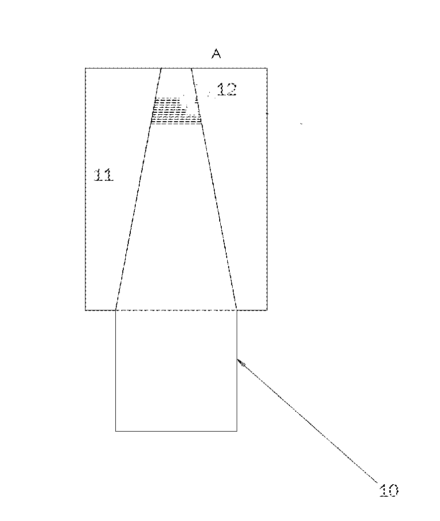
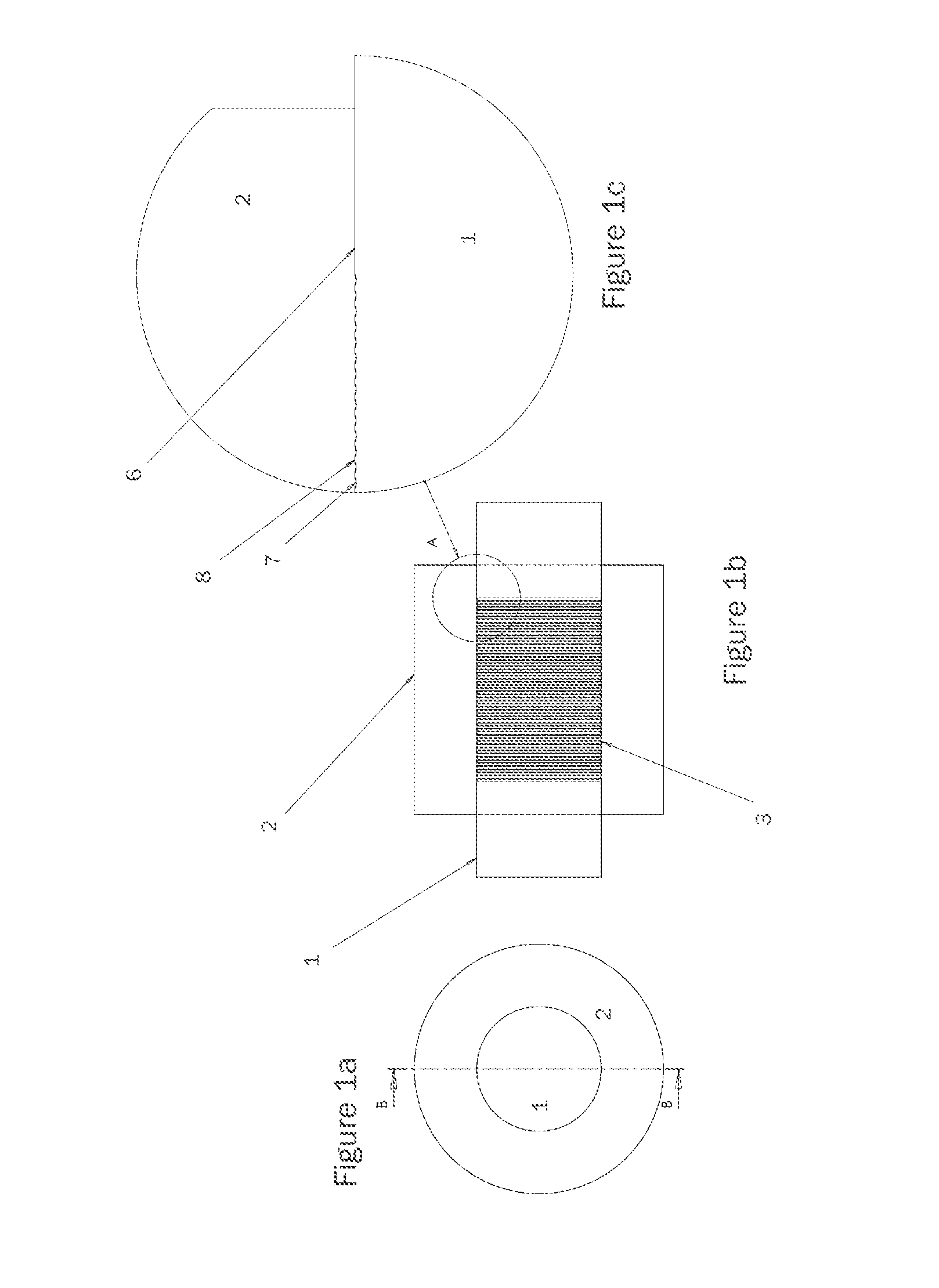
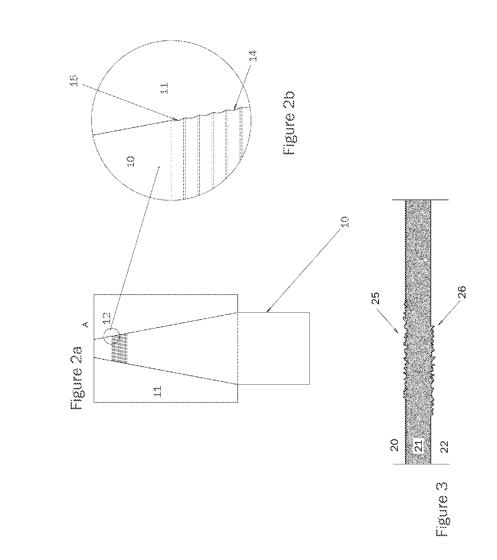
[0055]FIGS. 1a-c illustrate a preferred embodiment of a piston of mild steel (2) fitted to a hardened shaft (1). Concentric grooves (3) are formed into the shaft to create a roughened keyed area. This may be performed pre- or post-hardening of the shaft.

[0056]In this embodiment, for example, for a 40 mm diameter shaft use a 0.1 mm fit with grooves 0.04 mm deep (0.08 mm diametrical) and 0.4 mm pitch. This leaves 0.1 mm of original shaft diameter.

[0057]For a 60 mm diameter use 0.15 mm fit with 0.06 mm with 0.6 mm pitch with, again, 0.1 mm original material left on shaft. This can be performed using a standard cutting tool with a 0.4 mm radius.

[0058]For this embodiment, typically the maximum depth would be limited to 0.15 mm deep on 150 mm and larger shafts, but there is no actual limit. Ideally we do not exceed the “Fit” so the components are always held tight.

[0059]The outer piston (2) is heated and slid over the shaft (1) using standard interference fit techniques. In FIG. 1c we can...


PUM

PropertyMeasurementUnit
depthaaaaaaaaaa
depthaaaaaaaaaa
diameteraaaaaaaaaa

Abstract

An improved method of shrink fit assembly of two components increases resistance to torsional and / or axial loads without the need for a separate key element. Use of a roughened surface, in combination with a softer deformable material, creates a keyed type interaction at the contact areas of the shrink fitted components. One of the shrink fitted components may include the softer material, though intermediate layers and sleeves can be used.

Description

FIELD OF INVENTION[0001]The present invention is directed to a method for increasing the bond, and decreasing the likelihood of slipping, between shrink fitted components.BACKGROUND DESCRIPTION[0002]Shrink-fitting is a common technique for fitting components, and generally ensures a tighter union than interference fit items. In shrink fitting a temperature differential is created between parts to be fitted—e.g. one component is heated, or one element is cooled. The degree of heating or cooling depends on the coefficient of expansion of the component, and sometimes one component may be heated, while the other is cooled. The heating or cooling causes the elements to expand or shrink and enable them to be fitted. Upon returning to normal temperatures a tight fit is generated. An example might be a sleeve or piston shrink fitted to a cylindrical shaft. The shaft could be cooled, and / or the sleeve heated and then assembled. When returning to normal temperature a tighter union is formed t...

Claims


Application Information

Patent Timeline
Patent Type & Authority Applications(United States)
IPC IPC(8): B23P11/02B32B3/06
CPCB23P11/025F16B2/005Y10T428/24355Y10T29/49865F16B4/006F15B15/1447F15B2215/305B21D39/00
Inventor SHARP, RODNEY WARWICK
Owner PROGRESSIVE IP
Why Eureka
Try Eureka