Method for laser marking and laser marking system

a laser marking and laser marking technology, applied in the field of laser marking and laser marking system, can solve the problems of insufficient power, and insufficient laser marking power to achieve the effect of high speed and high resolution

Inactive Publication Date: 2012-07-19
TETRA LAVAL HLDG & FINANCE SA
View PDF6 Cites 30 Cited by
  • Summary
  • Abstract
  • Description
  • Claims
  • Application Information

AI Technical Summary

Benefits of technology

[0011]The inventive method is further defined in the dependent claims 2-8.
[0012]The invention also relates to laser marking system.
[0013]The laser marking system is further defined in the dependent claims 10-16.

Problems solved by technology

However, the systems are too slow or give too low resolution.
However, present laser diode arrays on the market are low energy lasers with an effect around or lower than 0.5 Watts.
These have proven to be insufficient.
It has been realized that the power is not enough to do marking at a speed higher than 1 meter per second.
Such equipment also limits the marking speed and resolution.
Presently, a system including a Galvanometer scanner is not applicable for marking at such high speed as 1.2 meters per second.
Today there are not any high energy laser diode arrays (lasers with an effect above 0.5 Watts) available on the market.
A laser diode array could be turned into a high energy laser, but it will only provide low resolution since the diodes may not be mounted sufficiently close to each other in a monolithic array.
Another difficulty is the cooling system of such a laser.

Method used


Image

  • Method for laser marking and laser marking system
  • Method for laser marking and laser marking system

Examples


example 1

[0039]An area of 8*7 mm of a substrate was coated with ink A. The laser energy density was set to 1.4 and 2.0 J / cm2, respectively, and the power density of the IR halogen lamp was set to 0.79 W / cm2. The optical density was then measured versus IR exposure time for the different laser energy densities. The test results indicated that utilizing a laser energy density of 1.4 J / cm2 together with the IR energizing element ands optical density of 0.6 was obtained. This corresponds to the use of a background laser energy density of 2.6 J / cm2, i.e. a decrease of 46% of laser energy needed for marking.

[0040]Further, the test results indicated that utilizing a laser energy density of 2.0 J / cm2 together with the IR energizing element ands optical density of 0.75 was obtained. This corresponds to the use of a background laser energy density of 2.8 J / cm2, i.e. a decrease of 29% of laser energy needed for marking.

example 2

[0041]An area of 8*7 mm of a substrate was coated with ink B. The laser energy density was set to 0.38 and 0.6 J / cm2, respectively, and the power density of the IR halogen lamp was set to 0.79 W / cm2. The optical density was then measured versus IR exposure time for the different laser energy densities. The test results indicated that utilizing a laser energy density of 0.38 J / cm2 together with the IR energizing element ands optical density of 1.0 was obtained. This corresponds to the use of a background laser energy density of 0.6 J / cm2, i.e. a decrease of 36% of laser energy needed for marking.

[0042]Further, the test results indicated that utilizing a laser energy density of 0.6 J / cm2 together with the IR energizing element ands optical density of 2.2 was obtained. This corresponds to the use of a background laser energy density of 1.4 J / cm2, i.e. a decrease of 57% of laser energy needed for marking.

[0043]Although the present invention has been described with respect to a presently...


PUM


Abstract

A method for laser marking a substrate provided with a laser sensitive area using a laser, wherein the laser sensitive area is adapted to be activated at a threshold energy level, the method comprising: energizing the laser sensitive area by an energizing element irradiating the complete laser sensitive area, and exposing a portion of the laser sensitive area to irradiation from the laser, wherein the energizing element is configured to emit radiation being concentrated at a specific wavelength, and wherein the combined irradiation results in an energy passing the threshold energy level such that the laser sensitive area is activated at the portion where combined irradiation has occurred. The invention is also related to a laser marking system for carrying out the method.

Description

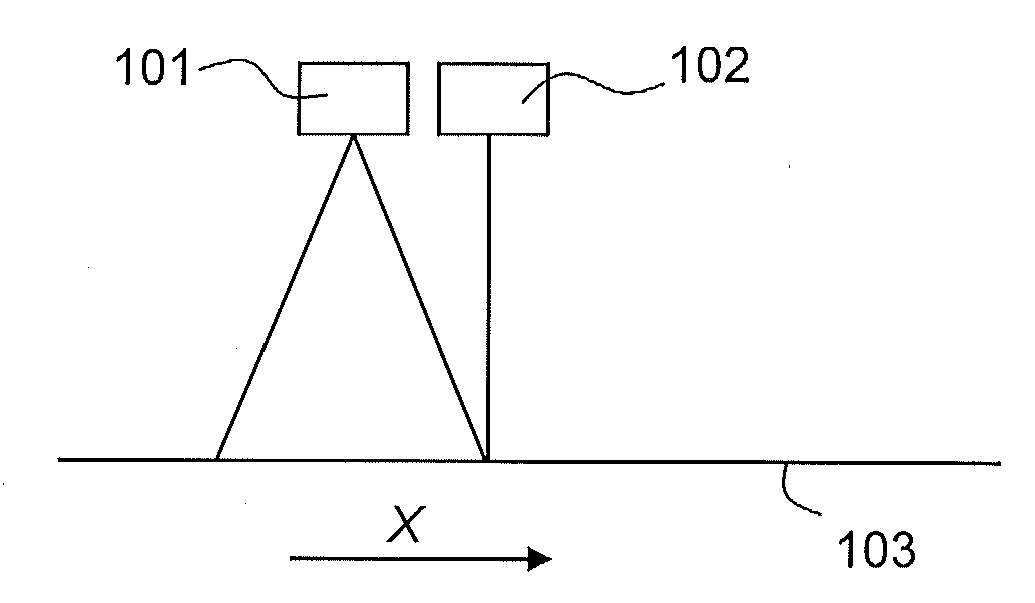
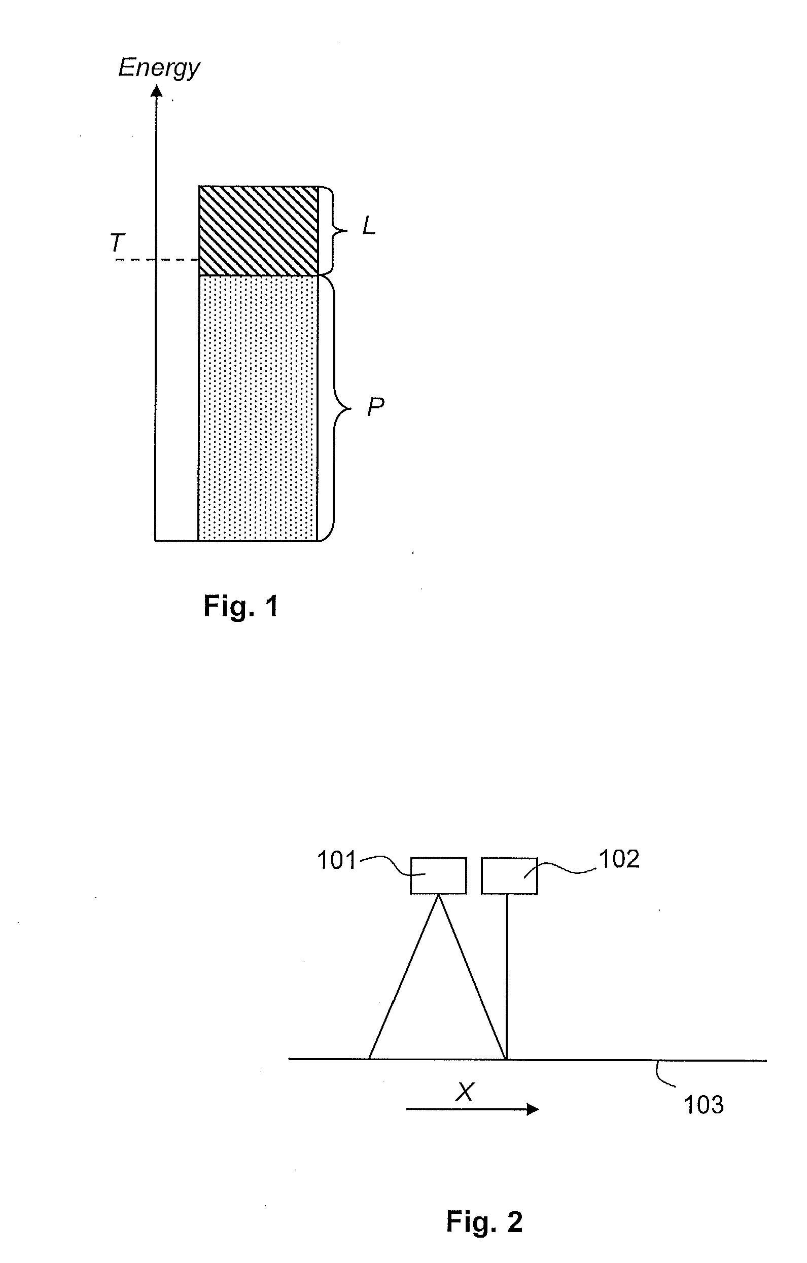
TECHNICAL FIELD[0001]The present invention relates to a method for laser marking and a laser marking system.TECHNICAL BACKGROUND[0002]There are different ways of marking substrates, such as for example packaging material, with alphanumerical numbers or codes, two dimensional codes, symbols, text, images etc. One way is to use laser technology; i.e. to use a laser and laser sensitive inks, coatings or pigments. Hereinafter such technology is denoted “laser marking”.[0003]The published document SE 0800601 describes laser marking of a packaging material with a core layer of paper or paper board.[0004]Laser sensitive ink or coating, hereinafter denoted “ink”, is a mix of laser light absorbers and colour formers. Upon exposure of laser light the light absorbers in the ink absorb the photon energies and create heat, which heat ignites the colour formers changing their colour.[0005]A substrate such as a packaging material may be provided with a laser sensitive area, i.e. an area provided w...

Claims


Application Information

Patent Timeline
Patent Type & Authority Applications(United States)
IPC IPC(8): B41J2/47
CPCB41J2/475B41J2/4753B41M5/30B41M5/28B41M5/26
Inventor SHOURVARZI, ABOLGHASEMBORJESSON, CECILIA
Owner TETRA LAVAL HLDG & FINANCE SA
Why Eureka
Try Eureka