Omnidirectional LED based solid state lamp

a solid-state lamp and led-based technology, applied in the field of illumination arts, lighting arts, solid-state lighting arts, can solve the problems of increased cost, complicated manufacturing, and certain devices

Inactive Publication Date: 2012-07-19
GE LIGHTING SOLUTIONS LLC
View PDF3 Cites 26 Cited by
  • Summary
  • Abstract
  • Description
  • Claims
  • Application Information

AI Technical Summary

Benefits of technology

[0008]In some embodiments disclosed herein as illustrative examples, an apparatus comprises a light engine comprising first and second light emitting diode (LED) devices or planar LED device arrays arranged to emit light in opposite directions, and a surrounding envelope including phosphor. The light engine is disposed at the center of the surrounding envelope, and the phosphor is effective to convert light emitted by the light engine to emission light. In some such apparatus, the light engine is bilaterally symmetric about a symmetry plane with the first LED device or planar LED device array and the second LED device or planar LED device array on opposite sides of the symmetry plane. In some such apparatus, each of the first and second LED devices or planar LED device arrays is configured to emit light having a uniform intensity distribution over a hemispherical solid angle except proximate to the symmetry plane. In some such apparatus each of the first and second LED devices or planar LED device arrays comprises at least one hemispherically emitting LED device including an LED chip and an encapsulant encapsulating the LED chip and shaped to refract light emitted by the LED chip into a uniform distribution over a hemispherical solid angle.
[0009]In some embodiments disclosed herein as illustrative examples, an apparatus comprises a bilaterally symmetrical light engine comprising first and second light emitting diode (LED) devices or planar LED device arrays facing opposite directions, and an envelope including phosphor spaced apart from and surrounding the bilaterally symmetrical light engine. The phosphor is effective to convert light emitted by the light engine to emission light. In some such apparatus, the bilaterally symmetrical light engine is configured to emit light having a bilaterally symmetrical intensity distribution that is uniform except at emission angles within 10° of the symmetry plane of the bilaterally symmetrical light engine.
[0010]In some embodiments disclosed herein as illustrative examples, an apparatus comprises: a bilaterally symmetrical light engine comprising first and second light emitting diode (LED) devices or planar LED device arrays facing opposite directions and configured to emit light having a bilaterally symmetrical intensity distribution that is uniform except at emission angles within 10° of the symmetry plane of the bilaterally symmetrical light engine; a surrounding envelope including phosphor, the light engine disposed at the center of and spaced apart from the surrounding envelope, the phosphor being effective to convert light emitted by the light engine to emission light; and a post passing through the surrounding envelope, the bilaterally symmetrical light engine being mounted on an end of the post.

Problems solved by technology

However, a problem with LED devices is that they tend to emit a forward-directed and “peaked” light distribution, for example a Lambertian light distribution, whereas many lamps and lighting applications call for omnidirectional illumination.
However, such devices have certain disadvantages.
Manufacturing is complicated since the mounting surface must be formed with the requisite three-dimensional shape and must include printed circuit traces or other wiring for electrically interconnecting the LED devices over this three-dimensional surface.
This increases cost as compared with using a fewer number of high power LED devices.
While such a device can emit omnidirectional illumination, it may be difficult to design the device to meet more stringent omnidirectional light distribution specifications.
While such a device can emit omnidirectional illumination, it may be difficult to design the device to meet more stringent omnidirectional light distribution specifications, especially with respect to latitude angles greater than 180°.
Further, it is difficult to extend the approach to lamps employing multiple LED devices.

Method used


Image

  • Omnidirectional LED based solid state lamp
  • Omnidirectional LED based solid state lamp
  • Omnidirectional LED based solid state lamp

Examples


Embodiment Construction

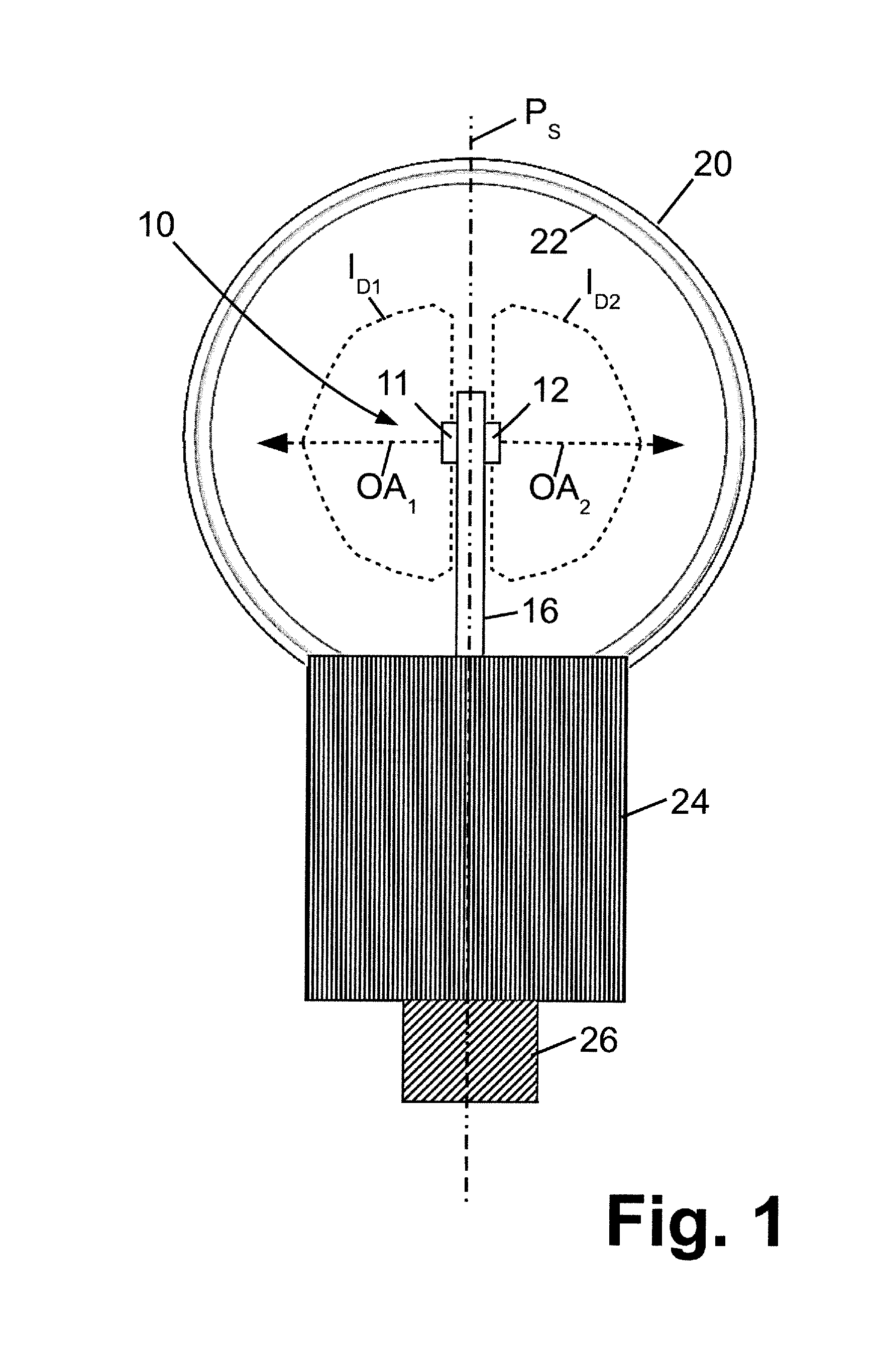
[0016]With reference to FIG. 1, a lamp or other lighting apparatus includes a light engine 10 comprising a first light emitting diode (LED) device or LED device array 11 and a second, oppositely facing LED device or LED device array 12. The light engine 10 is mounted on the end of a post 16 and is surrounded by an envelope 20 including a phosphor 22 that is effective to convert light emitted by the light engine 10 to emission light. In some embodiments, the light engine 10 emits blue, violet, or ultraviolet light and the phosphor 22 converts the blue, violet, or ultraviolet light emitted by the light engine 10 to white emission light. In some embodiments, a portion of the light emitted by the light engine 10 passes through the phosphor 22 to contribute to the emission light. For example, the light engine 10 may emit blue or violet light, the phosphor 22 may be tuned to emit warm white light (that is, white light with a spectrum that is biased toward the red end), and a portion of th...


PUM

PropertyMeasurementUnit
emission anglesaaaaaaaaaa
symmetryaaaaaaaaaa
angleaaaaaaaaaa

Abstract

A lighting apparatus includes a bilaterally symmetrical light engine comprising first and second light emitting diode (LED) devices or planar LED device arrays facing opposite directions, and an envelope including phosphor spaced apart from and surrounding the bilaterally symmetrical light engine. The phosphor is effective to convert light emitted by the light engine to emission light. The bilaterally symmetrical light engine may be configured to emit light having a bilaterally symmetrical intensity distribution that is uniform except at emission angles within 10° of the symmetry plane of the bilaterally symmetrical light engine. Each of the first and second LED devices or planar LED device arrays may comprise at least one hemispherically emitting LED device including an LED chip and an encapsulant encapsulating the LED chip and shaped to refract light emitted by the LED chip into a uniform distribution over a hemispherical solid angle.

Description

BACKGROUND[0001]The following relates to the illumination arts, lighting arts, solid-state lighting arts, and related arts.[0002]Light emitting diode (LED) devices are known for lighting applications. However, a problem with LED devices is that they tend to emit a forward-directed and “peaked” light distribution, for example a Lambertian light distribution, whereas many lamps and lighting applications call for omnidirectional illumination. An ideal omnidirectional illuminator would generate light with precisely the same intensity in every direction over a full sphere. As used in the lighting arts, the term “omnidirectional” illumination encompasses practical approximations to the ideal omnidirectional illumination. By way of illustrative example, some incandescent lamps considered to be omnidirectional light sources provide illumination across the latitude span θ=[0°, 135°] which is uniform to within about ±20% as specified in the proposed Energy Star standard for Integral LED Lamps...

Claims


Application Information

Patent Timeline
Patent Type & Authority Applications(United States)
IPC IPC(8): F21V9/16
CPCF21K9/135F21V5/04F21Y2101/02G02B19/0066G02B19/0071G02B19/0028F21V29/74F21V3/0418F21V3/0436F21V3/0472F21V3/0481F21V29/006F21K9/56F21V29/51F21K9/232F21K9/64F21Y2107/90F21Y2115/10F21V3/061F21V3/062F21V3/10F21V3/12F21S4/00
Inventor KOLODIN, BORISKUENZLER, GLENN H.ALLEN, GARY R.MAYER, MARK J.CAO, YIYU
Owner GE LIGHTING SOLUTIONS LLC
Why Eureka
Try Eureka