Detection apparatus

a technology of detection apparatus and detection device, which is applied in the direction of engine controllers, machines/engines, electric control, etc., can solve the problem of prolonging the regeneration process and achieve the effect of high accuracy

Active Publication Date: 2012-07-26
DENSO CORP
View PDF9 Cites 15 Cited by
  • Summary
  • Abstract
  • Description
  • Claims
  • Application Information

AI Technical Summary

Benefits of technology

[0024]According to this, while the regeneration process is performed, the attached amount of particulate matter is calculated at any time, and, when the calculation value becomes smaller than the predetermined value, the regeneration process is completed. Due to this, the regeneration process can be completed at optimum timing using the attached amount of particulate matter of high accuracy that is calculated at any time while the regeneration process is performed. Therefore, the regeneration process can be completed at optimum timing, thereby being able to realize a detection apparatus that can be regenerated, avoiding excess PM burning, unnecessarily long regeneration periods, and PM remaining after PM sensor regeneration.
[0025]The detection apparatus may further comprise a temperature detection unit that detects a temperature of the exhaust gas which flows through the exhaust path. The second setting unit may include a seventh setting unit that sets the completion timing of the regeneration process so that the period of the ...

Problems solved by technology

Further, as the amount of particulate matter which attaches to the attachment element becomes larger or the temperature of the...

Method used


Image

  • Detection apparatus
  • Detection apparatus
  • Detection apparatus

Examples


first embodiment

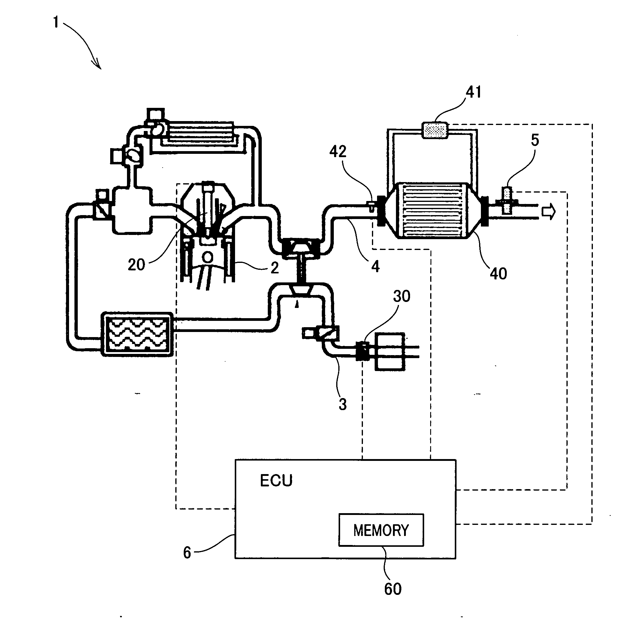
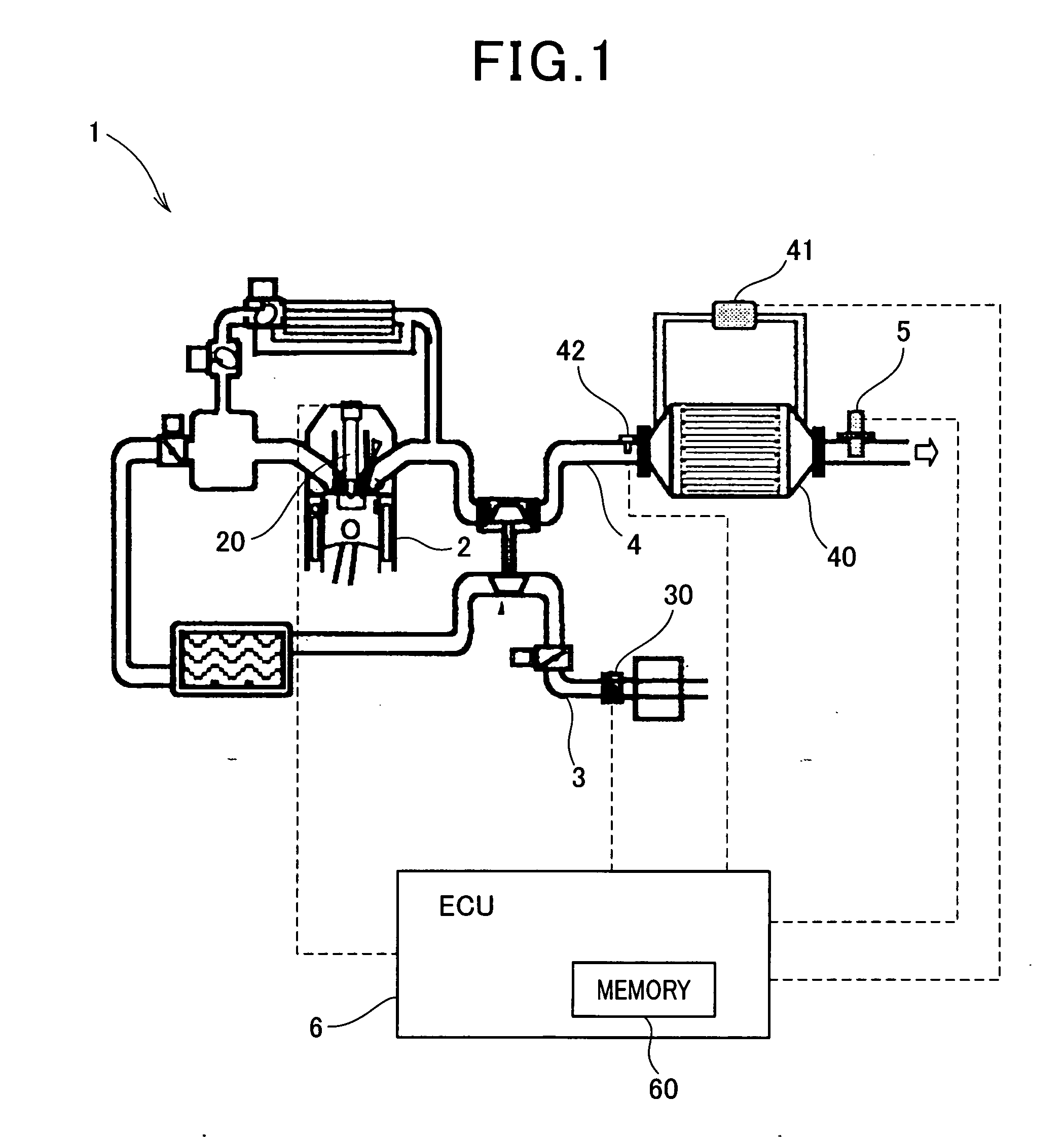
[0054]FIG. 1 is a schematic diagram illustrating a detection system (detection apparatus) 1 according to a first embodiment of the present invention. The detection system 1 may be applied to e.g., an automotive vehicle.

[0055]The detection system 1 is a system that detects an amount of PM flowing through an exhaust pipe (exhaust path) 4 of a diesel engine 2 (engine) that is an internal combustion engine. The detection system 1 includes an intake pipe 3, the exhaust pipe 4, a PM sensor 5, and an electronic control unit 6. Through the intake pipe 3, intake gas (air) is supplied to the engine 2. The intake pipe 3 is provided with an air flow meter 30 that detects an intake volume (e.g., a mass flow rate per unit time). In a cylinder of the engine 2, fuel is injected by an injector 20.

[0056]The exhaust pipe 4 is provided with a DPF 40, a differential-pressure meter 41, and an exhaust gas temperature sensor 40. The DPF 40 collects PM emitted by the engine 2. The differential-pressure mete...

second embodiment

[0071]Next, a second embodiment of the present invention is described. In the second embodiment, while the regeneration process is performed, the attached amount of the remaining PM in the PM sensor is calculated, the target electrode temperature is adjusted based on the attached amount of the remaining PM during the regeneration, and the regeneration period is also adjusted based on the electrode temperature during the regeneration.

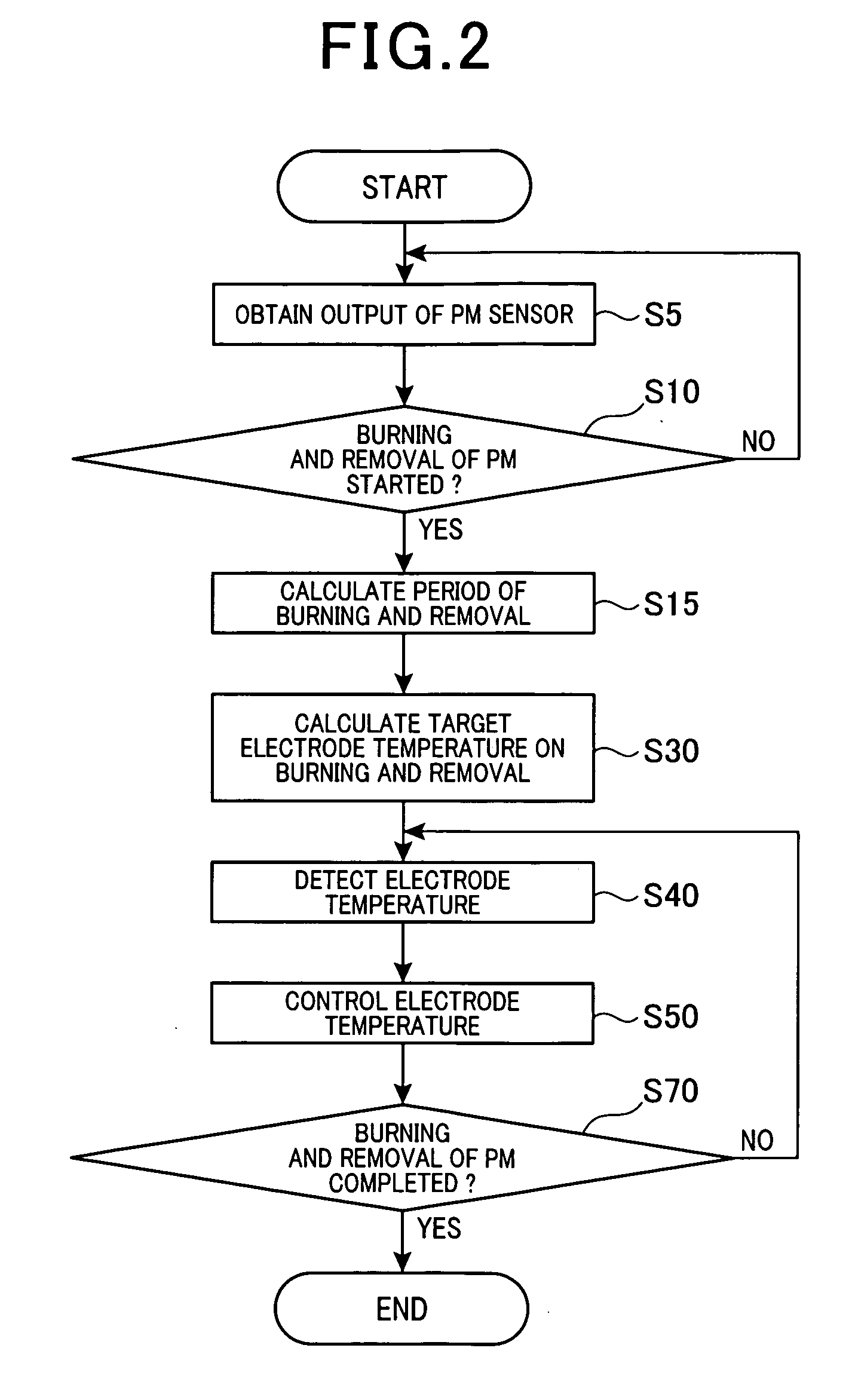
[0072]The configuration of FIG. 1 is also used in the second embodiment. Hereinafter, a part of the second embodiment different from the first embodiment is described. In the second embodiment, processes in steps of a flowchart shown in FIG. 5, not FIG. 2, are executed. In the flowchart of FIG. 5, steps S5, S10, S30, S40, S50, and S70 (the same references as FIG. 2) are the same as that of FIG. 2. Step S15 of FIG. 2 is omitted from the flowchart of FIG. 5. In FIG. 2, steps S20, S60 and S65 are newly added and executed. At step S70, if the ECU 6 judges NO...

third embodiment

[0085]Next, a third embodiment of the present invention is described. In the third embodiment, the regeneration period is not calculated as the first and second embodiments, but the attached amount of the remaining PM in the PM sensor 5 during the regeneration process of the PM sensor 5 is calculated, and, if the attached amount of the remaining PM becomes sufficiently small, the regeneration process is completed. The configuration of FIG. 1 is also used in the third embodiment. Hereinafter, a part of the third embodiment different from the second embodiment is described.

[0086]In the third embodiment, processes in steps of a flowchart shown in FIG. 11, not FIG. 5, are executed. In the flowchart of FIG. 11, each steps S5, S10, S20, S30, S40, S50, and S65 (the same references as FIG. 2) is the same process as those of FIG. 5. Step S60 of FIG. 5 is omitted from the flowchart of FIG. 11, because the calculation of the regeneration period is unnecessary. The process in step S70 of FIG. 5...


PUM


Abstract

A detection apparatus includes a detection unit, a control unit, a first setting unit, and a second setting unit. The detection unit is disposed in an exhaust path through which an exhaust gas flows, and detects a correlation value correlated with an amount of particulate matter (PM) attaching to an attachment element. The control unit controls a temperature of the attachment element to follow a target temperature while a regeneration process is performed to heat the attachment element so as to burn PM. The first setting unit sets the target temperature to be lower, as the amount of PM becomes larger. The second setting unit sets a completion timing of the regeneration process so that a period of the regeneration process becomes longer, as the amount of PM becomes larger or a temperature of the attachment element becomes lower while the regeneration process is performed.

Description

CROSS-REFERENCE TO RELATED APPLICATION[0001]This application is based on and claims the benefit of priority from earlier Japanese Patent Application No. 2011-012689 filed Jan. 25, 2011, the description of which is incorporated herein by reference.BACKGROUND OF THE INVENTION[0002]1. Technical Field of the Invention[0003]The present invention relates to a detection apparatus, and in particular to a detection apparatus that detects an amount of particulate matter in an exhaust gas that flows through the exhaust path of an internal combustion engine.[0004]2. Related Art[0005]Recently, internal combustion engines are required to have superior exhaust purification performance. In diesel engines, in particular, removal of so-called exhaust particulates (particulate matter (PM)), such as black smoke, exhausted from the engines is of increasing importance. In order to remove PM, diesel engines are most commonly equipped with a diesel particulate filter (DPF) in the middle of the exhaust pipe...

Claims


Application Information

Patent Timeline
IPC IPC(8): F01N3/023
CPCF01N2560/05F02D41/1494F02D41/1466F01N2560/20
Inventor YAHATA, SHIGETOUENO, TOMOHIRO
Owner DENSO CORP
Why Eureka
Try Eureka