
Eureka
For R&D, Eureka makes reading and utilizing patents & technical documents easy.
Eureka AIR
Designed for self-driven R&D workflows. Generate viable solutions, solve complex R&D challenges, empower your innovation with AI.

Eureka Materials
Designed for material experts only. Revolutionize your material R&D, from search, analyze, to developing new materials.

TechResearch
Generate reliable direction feasibility study reports for your R&D in just a few steps.

TechSeek
Discover and master advanced knowledge NOW. Basics, ideas, possibilities, all at once.

TechMind
As an expert in R&D Theories, TechMind can generates customized viable solutions instantly.

TechRisk
Analyze your overall solution with one click, know your potential R&D risks in advance.

TechMonitor
Get weekly tech updates, stay abreast of the latest tech innovations and key insights.
Glass lathe
- Summary
- Abstract
- Description
- Claims
- Application Information
AI Technical Summary
Benefits of technology
Problems solved by technology
Method used
Image

Examples
embodiments
First Comparative Example
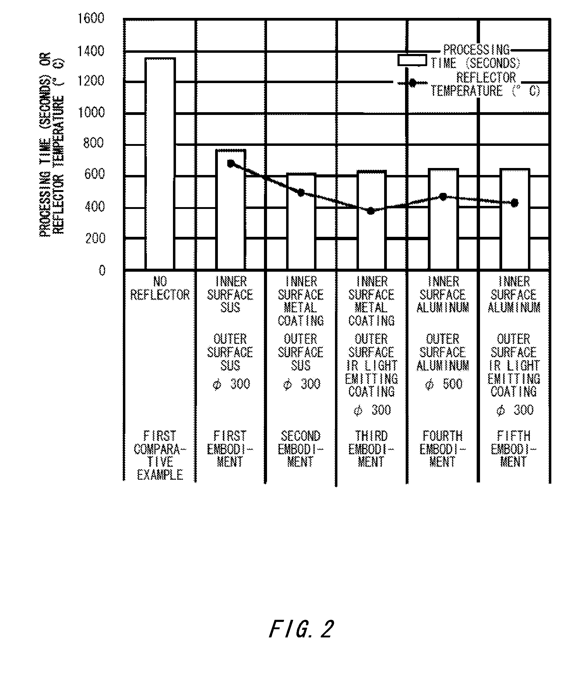
[0028]A quartz glass rod 2 with a diameter of 95 mm was disposed in a glass lathe, and drawn with a tensile force of 200 kgf while being heated in an oxygen flame having a hydrogen flow rate of 500 L / min and an oxygen flow rate of 250 L / min. The time needed to reach a 30 mm extension was measured to be 1360 seconds.
first embodiment
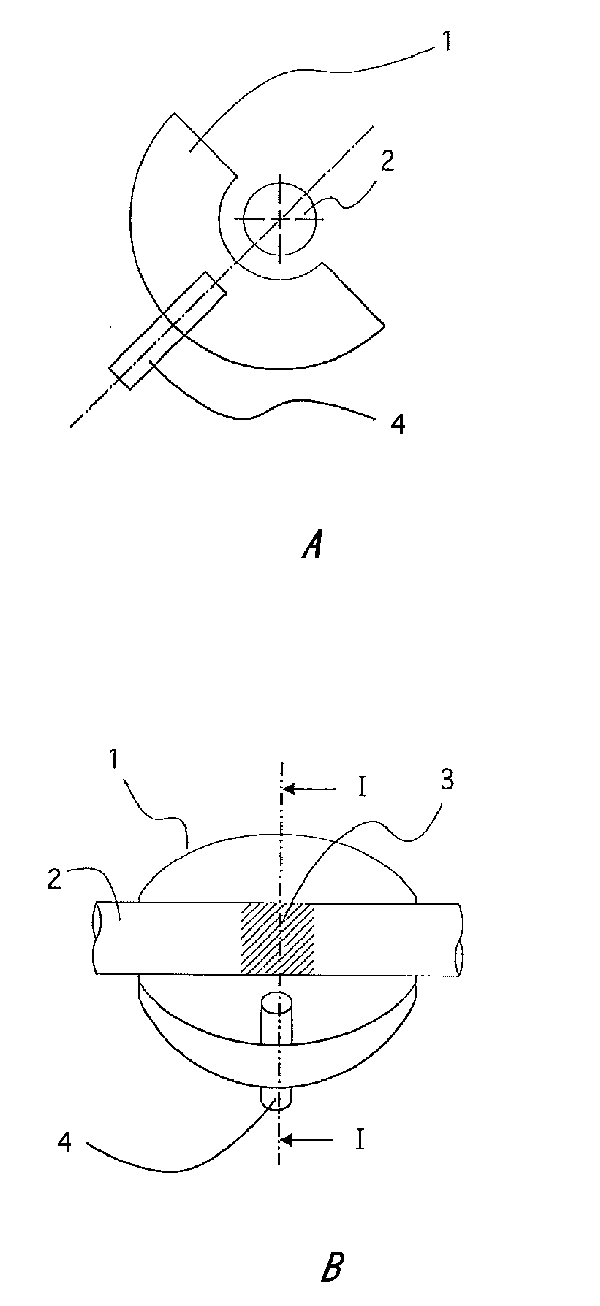
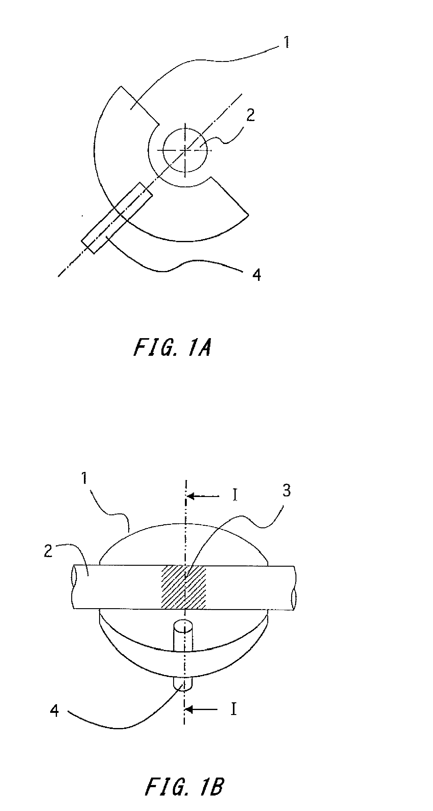
[0029]As shown in FIG. 1, a semi-spherical reflector 1 with a diameter of 300 mm and a polished inner surface made of SUS 304 was positioned below the quartz glass rod 2 in the glass lathe such that the spherical center of the reflector 1 substantially matches the center of the rotational axis of a quartz glass rod 2. The quartz glass rod 2 with a diameter of 95 mm was disposed in the glass lathe, and drawn with a tensile force of 200 kgf while being heated in an oxygen flame having a hydrogen flow rate of 500 L / min and an oxygen flow rate of 250 L / min. The time needed to reach a 30 mm extension was measured to be 765 seconds, thereby decreasing the time and amount of gas needed by 43.8% compared to the first comparative example. The outer surface temperature of the reflector 1 at this time was 683° C. The surface of the reflector 1 after processing was clean without soot stuck thereto, and could therefore be reused as is. It should be noted that deformation was observed in the surf...
second embodiment
[0030]A semi-spherical reflector 1 with a diameter of 300 mm and an inner surface made of SUS 304 and coated with metal was provided for the glass lathe, and all other conditions were the same as in the first embodiment. A quartz glass rod 2 with a diameter of 95 mm was disposed in the reflector 1 and drawn. The time needed to reach a 30 mm extension was measured to be 620 seconds, thereby decreasing the time and amount of gas needed by 54.4% compared to the first comparative example. The outer surface temperature of the reflector 1 at this time was 500° C. The surface of the reflector 1 after processing was clean without soot stuck thereto, and could therefore be reused as is. It should be noted that a portion of the metal plating was vaporized, and so there were locations where the SUS 304 base material was exposed.
PUM
| Property | Measurement | Unit |
|---|---|---|
| Thermal properties | aaaaa | aaaaa |
| Optical reflectivity | aaaaa | aaaaa |
Abstract
Description
Claims
Application Information
 - R&D Engineer
- R&D Manager
- IP Professional
- Industry Leading Data Capabilities
- Powerful AI technology
- Patent DNA Extraction
Browse by: Latest US Patents, China's latest patents, Technical Efficacy Thesaurus, Application Domain, Technology Topic, Popular Technical Reports.
© 2024 PatSnap. All rights reserved.Legal|Privacy policy|Modern Slavery Act Transparency Statement|Sitemap|About US| Contact US: help@patsnap.com