Vehicle hydraulic clutch apparatus

Inactive Publication Date: 2012-07-26
TOYOTA JIDOSHA KK +1
View PDF5 Cites 8 Cited by
  • Summary
  • Abstract
  • Description
  • Claims
  • Application Information

AI Technical Summary

Benefits of technology

[0028]According to the hydraulic clutch apparatus, since the flow restraint device is formed integrally with the cylindrical seat member that is inserted in the connecting portion between the concentric slave cylinder

Problems solved by technology

Then, due to influence of the inertia of the working oil,

Method used


Image

  • Vehicle hydraulic clutch apparatus
  • Vehicle hydraulic clutch apparatus
  • Vehicle hydraulic clutch apparatus

Examples


embodiment 1

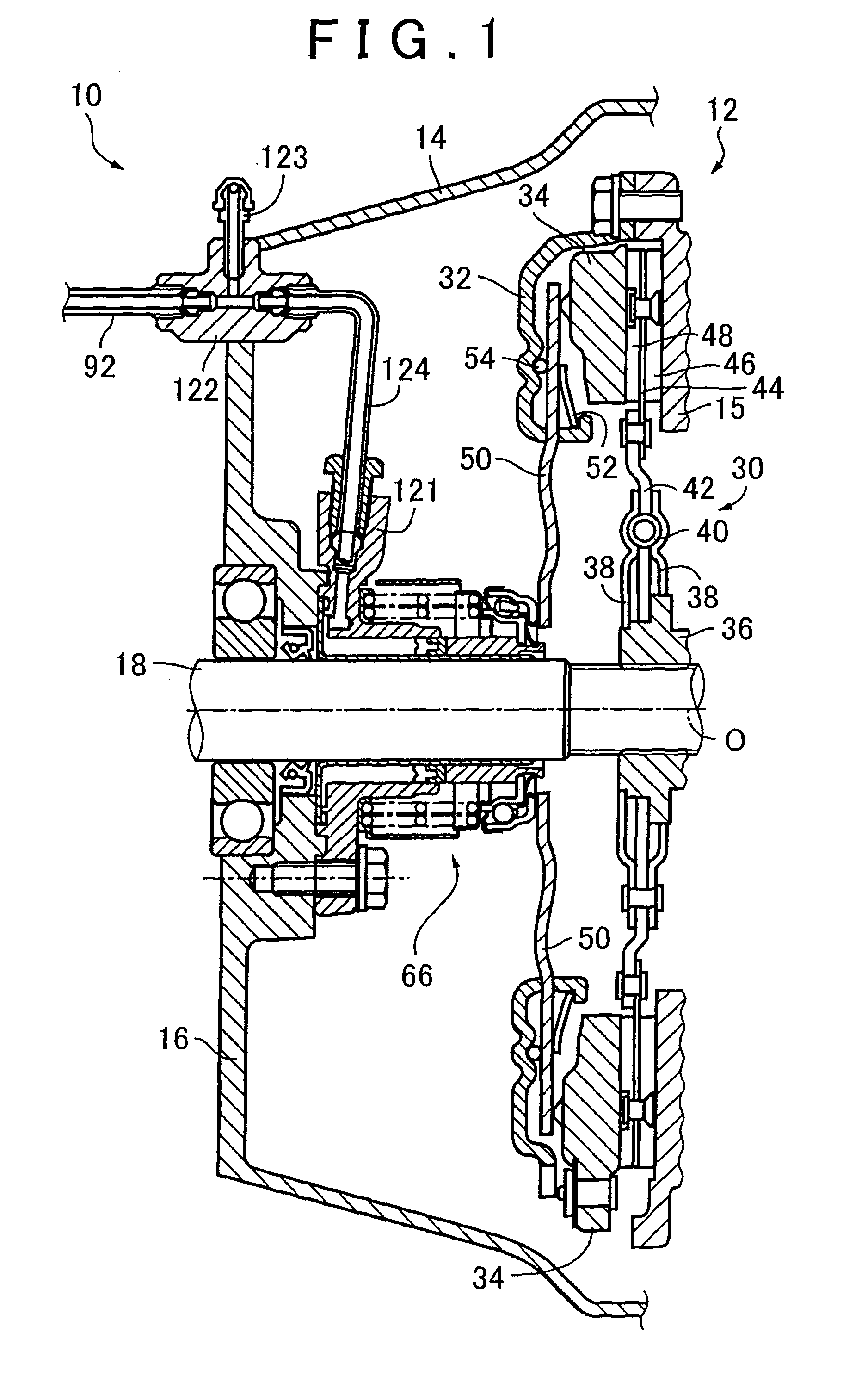
[0049]FIG. 1 is a sectional view showing a friction clutch 12 and its peripheral members that are provided in a vehicle equipped with a vehicle hydraulic clutch apparatus 10 in accordance with this embodiment of the invention. In FIG. 1, the friction clutch 12 is a dry-type single-plate disc clutch that constitutes a portion of a motive power transmission path from a drive force source of the vehicle to driving wheels, and functions as a friction coupling that transmits motive power by friction. In this embodiment, the friction clutch 12 is provided in a cylindrical clutch housing 14 that is connected integrally with an engine (not shown) that corresponds to the foregoing drive force source and also integrally with a housing of, for example, a well-known constant mesh parallel shaft-type manual transmission (not shown). Specifically, in the clutch housing 14, the friction clutch 12 is provided between the a circular plate-shaped flywheel 15 that is fixed to an end portion of an outp...

embodiment 2

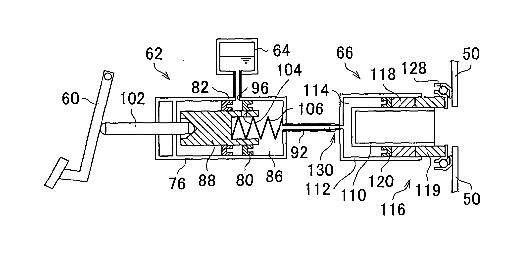
[0092]FIG. 16 is a diagram schematically showing a one-way throttle valve 200 (corresponding to a valve mechanism in the invention) as a flow restraint device provided in Embodiment 2 of the invention. In FIG. 16, a one-way throttle valve 200 is provided in an oil passageway connecting portion 134 between a piping 124 and an extended portion 121 of an outer sleeve 112, as in the foregoing embodiment. That is, the one-way throttle valve 200 is fitted, in place of the orifice 130 in Embodiment 1 described above, in the connecting portion 134 between the piping 124 and the extended portion 121. This one-way throttle valve 200 functions as a flow restraint device that restrains the flow of the working oil moving from the slave cylinder 66 side to the master cylinder 62 side which is caused in association with the operation of returning the clutch pedal 60 from the depressed state. The one-way throttle valve 200 is constructed so as to permit the working oil to flow from the master cylin...


PUM


Abstract

A vehicle hydraulic clutch apparatus includes a clutch master cylinder that generates clutch working oil pressure in response to operation of a clutch pedal, and a concentric slave cylinder that engages and releases a friction clutch as the clutch working oil pressure generated by the clutch master cylinder is supplied thereto and discharged therefrom via an oil passageway. A flow restraint device (130, 200) that restrains flow of the working oil from a concentric slave cylinder (66) side to a clutch master cylinder (62) side which occurs according to operation of the clutch pedal (60) is provided in the concentric slave cylinder (66).

Description

BACKGROUND OF THE INVENTION[0001]1. Field of the Invention[0002]The invention relates to a vehicle hydraulic clutch apparatus for transmitting motive power of a drive force source to a driving wheel and cutting off the transmission of motive power and, particularly, to a technology that improves the operability of the vehicle hydraulic clutch apparatus.[0003]2. Description of the Related Art[0004]A vehicle is equipped with a vehicle hydraulic clutch apparatus for selectively transmitting motive power generated by a drive force source to driving wheels and cutting off the transmission of motive power thereto. The vehicle hydraulic clutch apparatus uses oil pressure as a drive source. For example, when a clutch pedal is depressed by a driver of the vehicle, oil pressure is accordingly generated, and a friction clutch is actuated through the use of the generated oil pressure as a drive source so as to cut off the transmission of motive power.[0005]The friction clutch and the clutch ped...

Claims


Application Information

Patent Timeline
IPC IPC(8): F16D25/06
CPCF16D2048/0215F16D48/02F16D25/083F16D25/12
Inventor OTA, MASAYOSHIMIZUTA, ATSUHISAOKANO, NOBUHIKOSEGAWA, TAKEOKAGIYAMA, JUNJISADAKARI, SHUJIGOTOU, YUUICHIMATSUISHI, TAKASHINIWA, HIDEMICHIKOYANAGI, MAKOTO
Owner TOYOTA JIDOSHA KK
Why Eureka
Try Eureka