Spinal implant with padded bone engaging projections

a technology of bone engaging projection and spine, which is applied in the field of spine implant with padded bone engaging projection, can solve the problems of perplexing chronic low back pain

Inactive Publication Date: 2012-07-26
CHEN CLAIRE
View PDF3 Cites 43 Cited by
  • Summary
  • Abstract
  • Description
  • Claims
  • Application Information

AI Technical Summary

Problems solved by technology

Chronic low back pain is a perplexing p...

Method used


Image

  • Spinal implant with padded bone engaging projections
  • Spinal implant with padded bone engaging projections
  • Spinal implant with padded bone engaging projections

Examples


Embodiment Construction

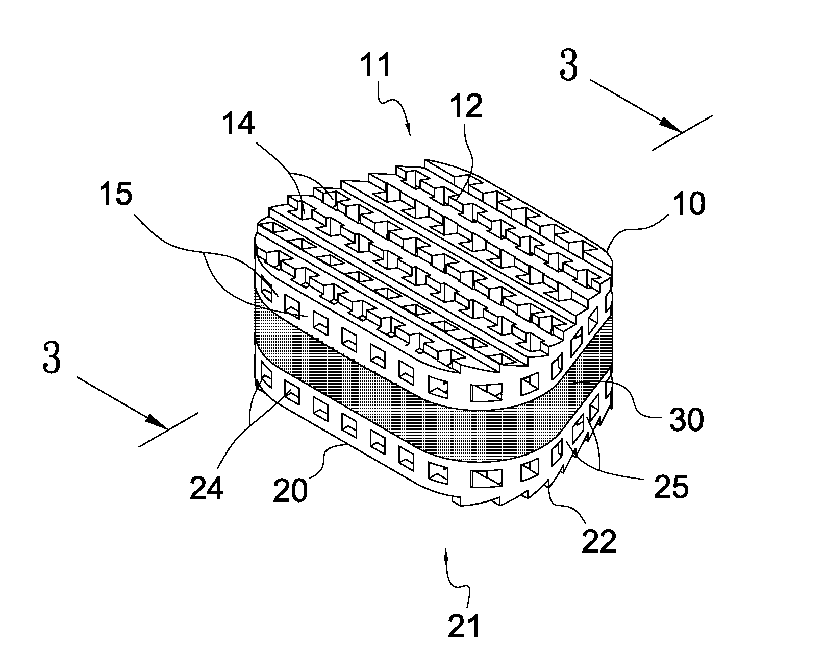
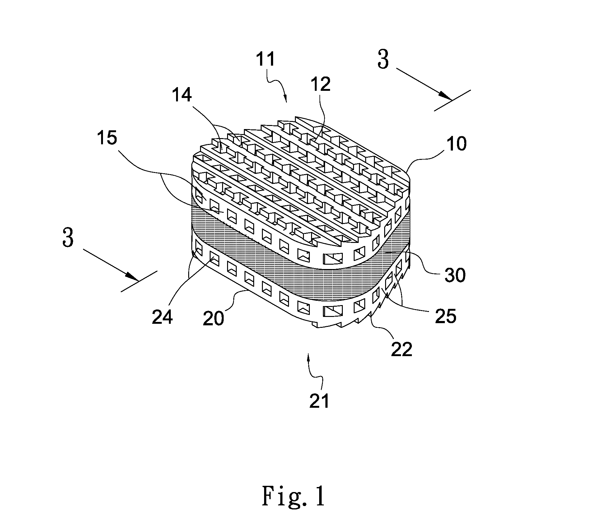
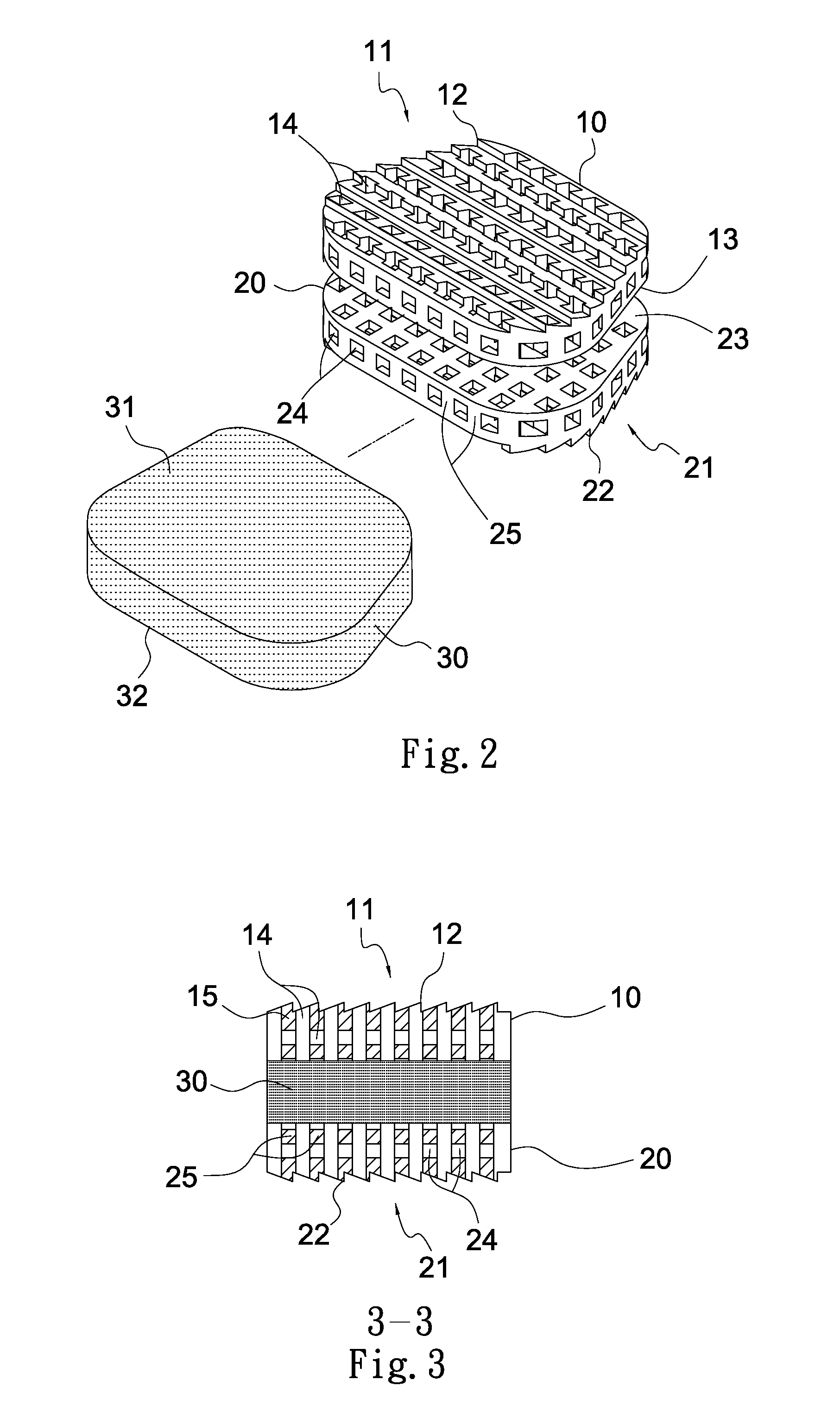
[0019]Referring to FIGS. 1 to 4, a spinal implant in accordance with a first preferred embodiment of the invention is shown. The spinal implant has a substantially rectangular cross section and comprises the following components as discussed in detail below.

[0020]An upper section 10 is formed of a composite material being sturdy and highly resistant to chemicals. The composite material may be carbon fiber or PEEK (polyetheretherketone). Alternatively, the upper section 10 is formed of alloy such as stainless steel, cobalt-chromium-molybdenum alloy, titanium, or titanium alloy. Still alternatively, the upper section 10 is formed of polymer such as UHMWPE (ultra high molecular weight polyethylene), PMMA (polymethylmethacrylate), silicon rubber, or ultra high molecular polyethylene. Still alternatively, the upper section 10 is formed of ceramic such as aluminum oxide, calcium phosphate tri-basic, or fiber glass.

[0021]The upper section 10 has a top surface 11 with a top retaining member...


PUM


Abstract

A spinal implant in one embodiment includes an implant for insertion between two opposite spaced vertebrae of a spine, comprising an upper section having a substantially rectangular cross section and comprising a toothed top retaining member and a peripheral surface; a lower section having a substantially rectangular cross section and comprising a toothed bottom retaining member and a peripheral surface; an intermediate padding member for fastening the upper section and the lower section together; two three-dimensional matrix structures formed in the upper section and the lower section respectively and on the peripheral surfaces of the upper section and the lower section respectively as support; and a plurality of holes formed through at least one of three directions of each of the three-dimensional matrix structures.

Description

BACKGROUND OF THE INVENTION[0001]1. Field of Invention[0002]The invention relates to surgical procedures for stabilizing the spine and more particularly to an improved implant having padded bone engaging projections for use in such procedure.[0003]2. Description of Related Art[0004]In human anatomy, the vertebral column (backbone or spine) is a column usually consisting of 24 articulating vertebrae (including 7 vertebrae in cervical region, 12 vertebrae in thoracic region, and 5 vertebrae in lumbar region) and 9 fused vertebrae in the sacrum and the coccyx. It is situated in the dorsal aspect of the torso, separated by intervertebral discs. It houses and protects the spinal cord in its spinal canal.[0005]Intervertebral discs lie between adjacent vertebrae in the spine. Each intervertebral disc forms a cartilaginous joint to allow slight movement of the vertebrae, and acts as a ligament to hold the vertebrae together. An intervertebral disc consists of an outer annulus fibrosus surro...

Claims


Application Information

Patent Timeline
IPC IPC(8): A61F2/44
CPCA61F2/30744A61F2310/00293A61F2002/30014A61F2002/30069A61F2002/30563A61F2002/30566A61F2002/30904A61F2002/30911A61F2002/443A61F2002/4495A61F2310/00017A61F2310/00023A61F2310/00029A61F2310/00203A61F2/4425
Inventor HUANG, MENG-FENG
Owner CHEN CLAIRE
Why Eureka
Try Eureka