Stacked Layer High Efficiency Solar Energy Collector

a solar energy collector and high-efficiency technology, applied in the field of solar energy collection, can solve the problems of system only capturing a fraction of solar energy, poor energy conversion efficiency, and relatively low efficiency, and achieve the effect of high-efficiency solar energy conversion module, and high-efficiency solar energy conversion

Inactive Publication Date: 2012-08-02
TOTAL ENERGY RENEWABLE POWER SYST
View PDF8 Cites 43 Cited by
  • Summary
  • Abstract
  • Description
  • Claims
  • Application Information

AI Technical Summary

Benefits of technology

[0011]In another embodiment, the present invention includes a stacked layer high efficient solar energy conversion module, comprising: a flexible photovoltaic layer; a flexible thermoelectric conversion layer coupled to the photovoltaic layer; a flexible fluid heating layer coupled to the thermoelectric conversion layer; and a flexible insulation layer, coupled to the flexible fluid heating layer, wherein the layers are sandwiched together and a finite length of the layer sandwich is rolled into a compact package.
[0012]In still another embodiment, the present invention includes a stacked layer high efficient solar energy conversion module, comprising: a flexible photovoltaic layer coupled to the protective layer; a flexible fluid heating layer coupled to the thermoelectric conversion layer; and a flexible insulation layer, coupled to the flexible fluid heating layer, wherein the layers are sandwiched together and a finite length of the layer sandwich is rolled into a compact package.
[0013]Another embodiment of the present invention relates to a modular solar power system, comprising a rail system and a stacked layer high efficient solar energy conversion module. The rail system further comprises: at least one pair of finite length lightweight material rails shaped into opposing channels; a first fluid conduit disposed within a channel of one of the at least one pair of rails; a second fluid conduit disposed within a channel of the opposing one of the at least one pair of rails; and a plurality of electrical conductors disposed within the channels of each of the at least one pair of rails. The stacked layer high efficient solar energy conversion module further comprises: a protective layer; a photovoltaic layer coupled to the protective layer with electrodes for communicating a generated voltage to a load; a thermoelectric conversion layer coupled to the photovoltaic layer electrodes for communicating a generated voltage to a load; a fluid heating layer coupled to the thermoelectric conversion layer with at least an inlet conduit and an outlet conduit; and a insulation layer, wherein the protective layer and the insulation layer together encompass the other layers, wherein the stacked layer high efficient solar energy conversion module is sized such that each module fits the rail system, and wherein, the first fluid conduit of the rail system is configured for connection to the inlet conduit of the fluid heating layer, the second fluid conduit of the rail system is configured for connection to the outlet conduit of the fluid heating system, and the electrodes from the photovoltaic and thermoelectric conversion layers are configured to connect to one or more of the plurality of electrical conductors of the rail system.

Problems solved by technology

One of the major drawbacks of solar cells is their relatively poor energy conversion efficiency (e.g., 12-18%) although recent advancements are improving this conversion efficiency.
Likewise, even the hybrid systems still only capture a fraction of the solar energy that they intercept.

Method used


Image

  • Stacked Layer High Efficiency Solar Energy Collector
  • Stacked Layer High Efficiency Solar Energy Collector
  • Stacked Layer High Efficiency Solar Energy Collector

Examples


Embodiment Construction

[0020]Reference will now be made in detail to embodiments of the present invention with reference to the accompanying figures, in which like reference numerals indicate like elements.

[0021]Embodiments of the present invention relate to methods and apparatus for capturing solar energy in relatively higher efficiency than known methods and providing a simpler packaging and installation design.

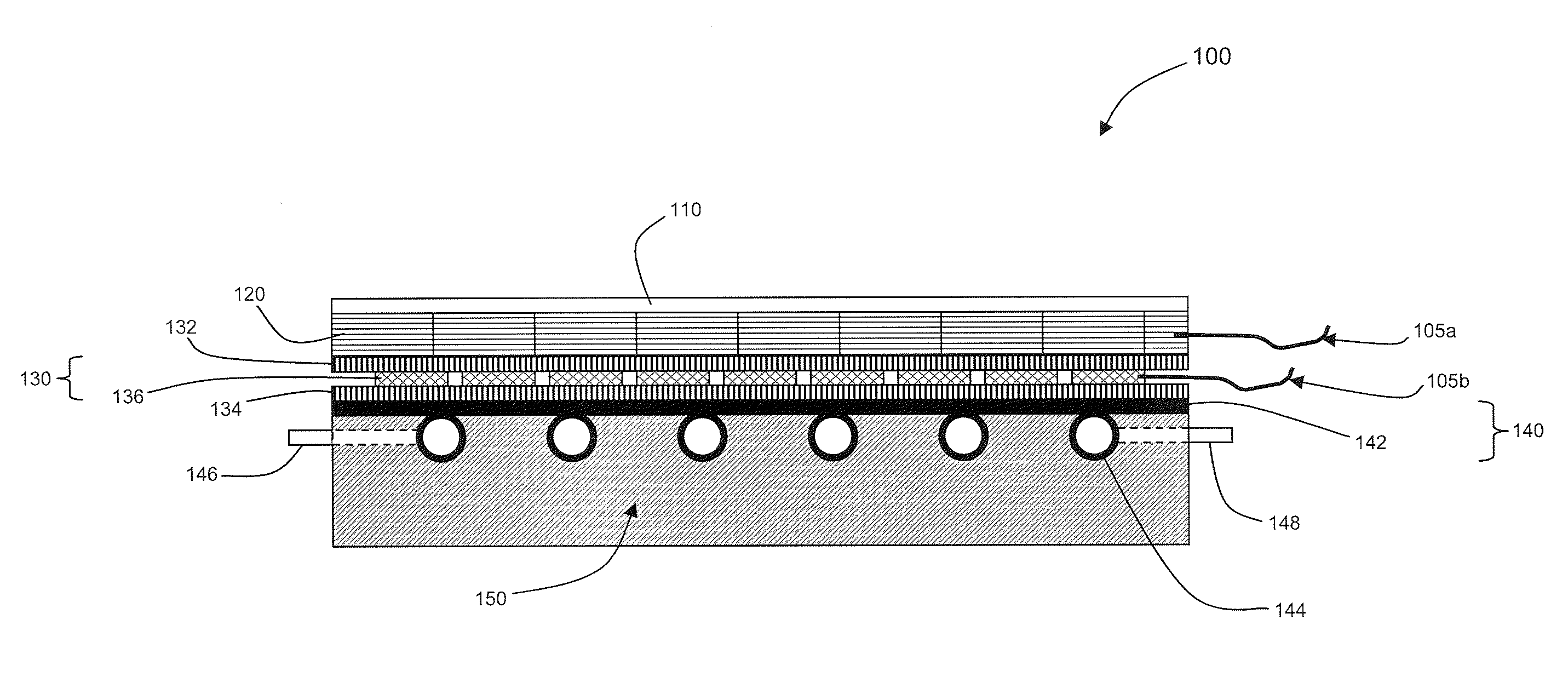
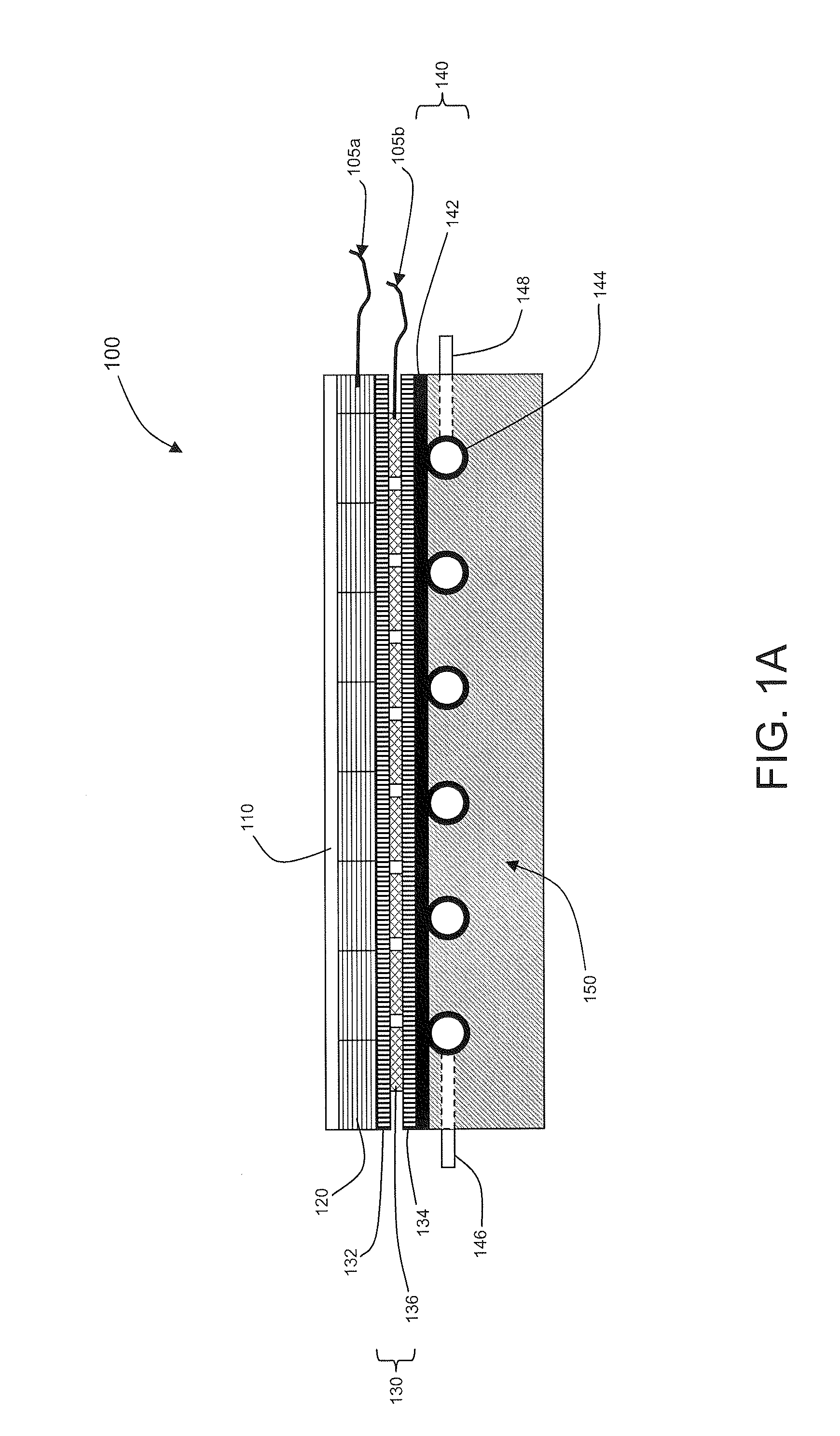
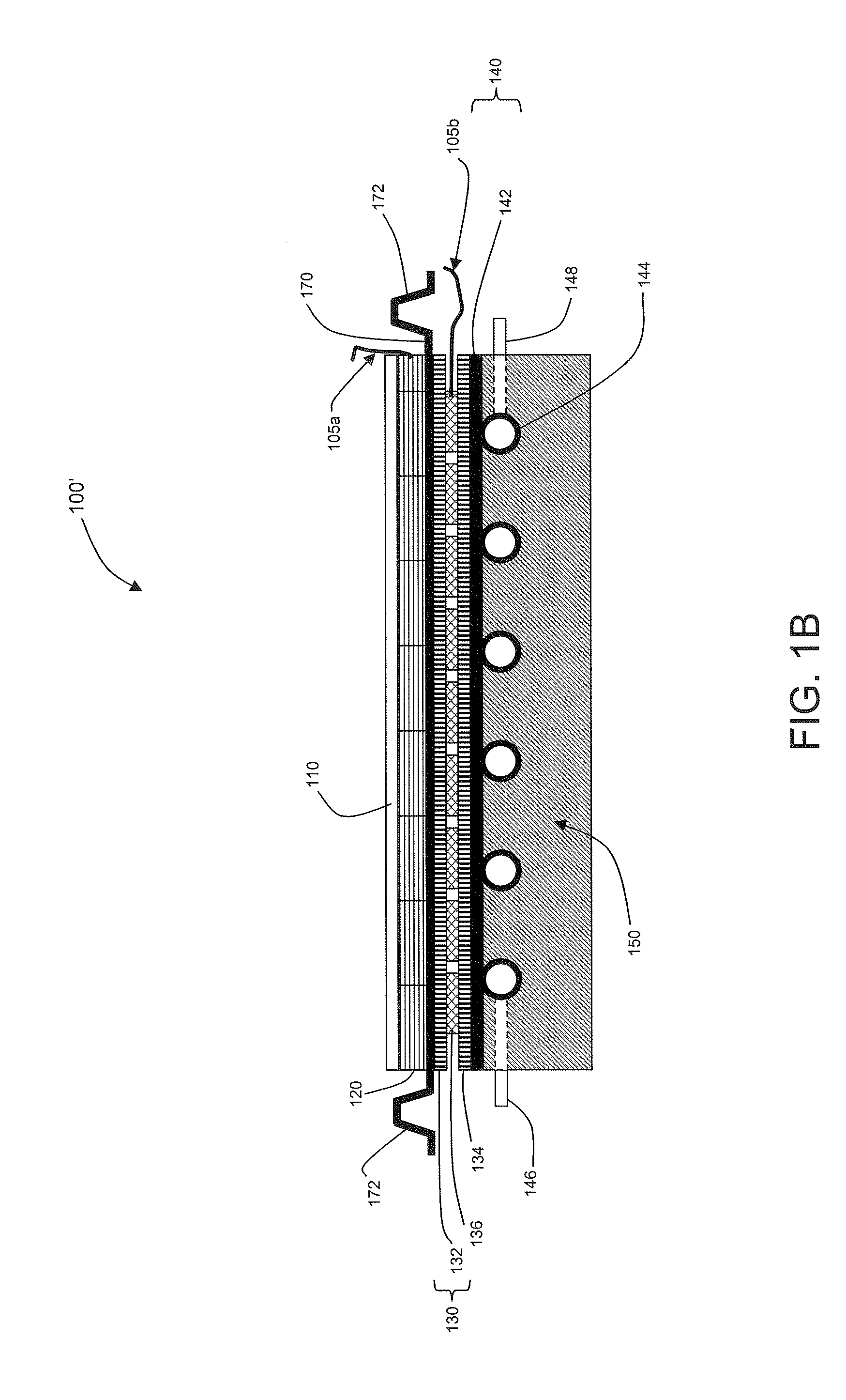
[0022]FIG. 1A is a diagram showing a cross-sectional view of an exemplary multi-stack solar energy collector panel 100. Multi-stack solar energy collector panel 100 can be part of an improved solar energy collection system (not shown) made according to an embodiment of the present invention. In one embodiment, multi-stack solar energy collector panel 100 can be used stand-alone to capture and process solar energy into electricity and a heated fluid, outputting a certain quantity of converted energy. In other embodiments, a plurality of exemplary multi-stack solar energy collector panels 100 can b...


PUM


Abstract

An apparatus for improving the efficiency and usability of a solar energy collection panel is provided. In one embodiment, the collection panel comprises a plurality of layers. The first layer is a photovoltaic layer that converts the solar energy into electricity. That layer is coupled to a thermoelectric conversion layer that sinks heat from the photovoltaic layer and generates electricity based on the temperature difference between the top and bottom of the layer. A fluid heating layer is then coupled to and sinks heat from the thermoelectric layer to heat up a fluid, e.g. air or water. Each of these layers is stacked together and placed above an insulation layer that supports the layers and thermally isolates them from the surrounding environment. In another embodiment, a flexible coiled solar energy collection panel is provided. In still another embodiment, a modular rail system is provided for simple and customizable installation.

Description

BACKGROUND OF THE INVENTION[0001]1. Field of the Invention[0002]The field of the present invention relates to solar energy collection.[0003]2. Background Art[0004]Solar energy has long been useful to mankind, but it is only in the relatively recent past that mankind's technological advancements have allowed for more “modern” ways to capture, convert, and utilize, in the form of electricity and / or thermal energy, more of the solar energy that enters the earth's atmosphere.[0005]One apparatus for converting this solar energy into electricity is a photovoltaic (PV) cell, or as it is more commonly known, a solar cell. Solar cells are semiconductors that are designed to produces electricity when exposed to light due to the photovoltaic effect. One of the major drawbacks of solar cells is their relatively poor energy conversion efficiency (e.g., 12-18%) although recent advancements are improving this conversion efficiency.[0006]Another known apparatus for capturing solar energy is known a...

Claims


Application Information

Patent Timeline
Patent Type & Authority Applications(United States)
IPC IPC(8): H01L31/052H01L31/048F24J2/04
CPCY02B10/20Y02B10/12H01L31/052H02S10/10Y02E10/60H01L35/30H02S40/44Y02E10/50H02S40/425Y02B10/10H10N10/13
Inventor MCCOWAN, WILLIAM PAULCHAPMAN, JR., JOHN SPENCE HAYESCHAPMAN, MICHAEL CHASEMYERS, DONALD GEORGEVANCE, BRUCE BARTON
Owner TOTAL ENERGY RENEWABLE POWER SYST
Why Eureka
Try Eureka