Energy efficient inductive power transmission system and method

a technology energy efficient, applied in the direction of inductance, circuit arrangement, safety/protection circuit, etc., can solve the problems of increasing energy cost, and affecting the efficiency of inductive power transmission

Active Publication Date: 2012-08-02
POWERMAT TECHNOLOGIES
View PDF6 Cites 82 Cited by
  • Summary
  • Abstract
  • Description
  • Claims
  • Application Information

AI Technical Summary

Benefits of technology

[0026]increasing operating power by a first increment if the signal detector detects a third instruction signal;
[0027]increasing operating power by a second increment if the signal detector detects a fourth instruction signal;

Problems solved by technology

On a global scale, there is increasing concern that the emission of greenhouse gases such as carbon dioxide from the burning of fossil fuels may precipitate global warming.
Moreover, energy resources are limited.
The scarcity of global energy resources alongside geopolitical factors drives the cost of energy upwards.
Energy losses in electrical energy transmission are chiefly due to the incidental heating of current carrying wires.
In many cases this is unavoidable, as current carrying wires are essential for the powering of electrical devices and current carrying wires have resistance.
In other cases the energy losses are unnecessary.
For example, electrical devices are often left running unnecessarily and energy used to power devices which are not being used is truly wasted.
Power losses due to the heating of a cable increase according to the square of the current it carries so energy losses from the cable may increase parabolically.
Furthermore, in the absence of effective energy management, if too many devices draw current from a single cable the current supplied may exceed the permitted level thereby tripping a circuit breaker or blowing a fuse.
Even more seriously, the excessive current may lead to overheating of the cable which is a common cause of fire.
A further unnecessary usage of energy is in powering of devices having onboard power cells.
Furthermore, the energy needlessly consumed charging electrical cells beyond the level necessary for operation of a device increases electricity bills.
This can be difficult to maintain as the resonant frequency of the system may fluctuate during power transmission, for example in response to changing environmental conditions or variations in alignment between primary and secondary coils.
Amongst others, one problem associated with resonant transmission is the high transmission voltages involved.
At high operating voltages, a large amount of heat may be generated by the system resulting in high power losses as well as damage to heat sensitive components.

Method used


Image

  • Energy efficient inductive power transmission system and method
  • Energy efficient inductive power transmission system and method
  • Energy efficient inductive power transmission system and method

Examples


Embodiment Construction

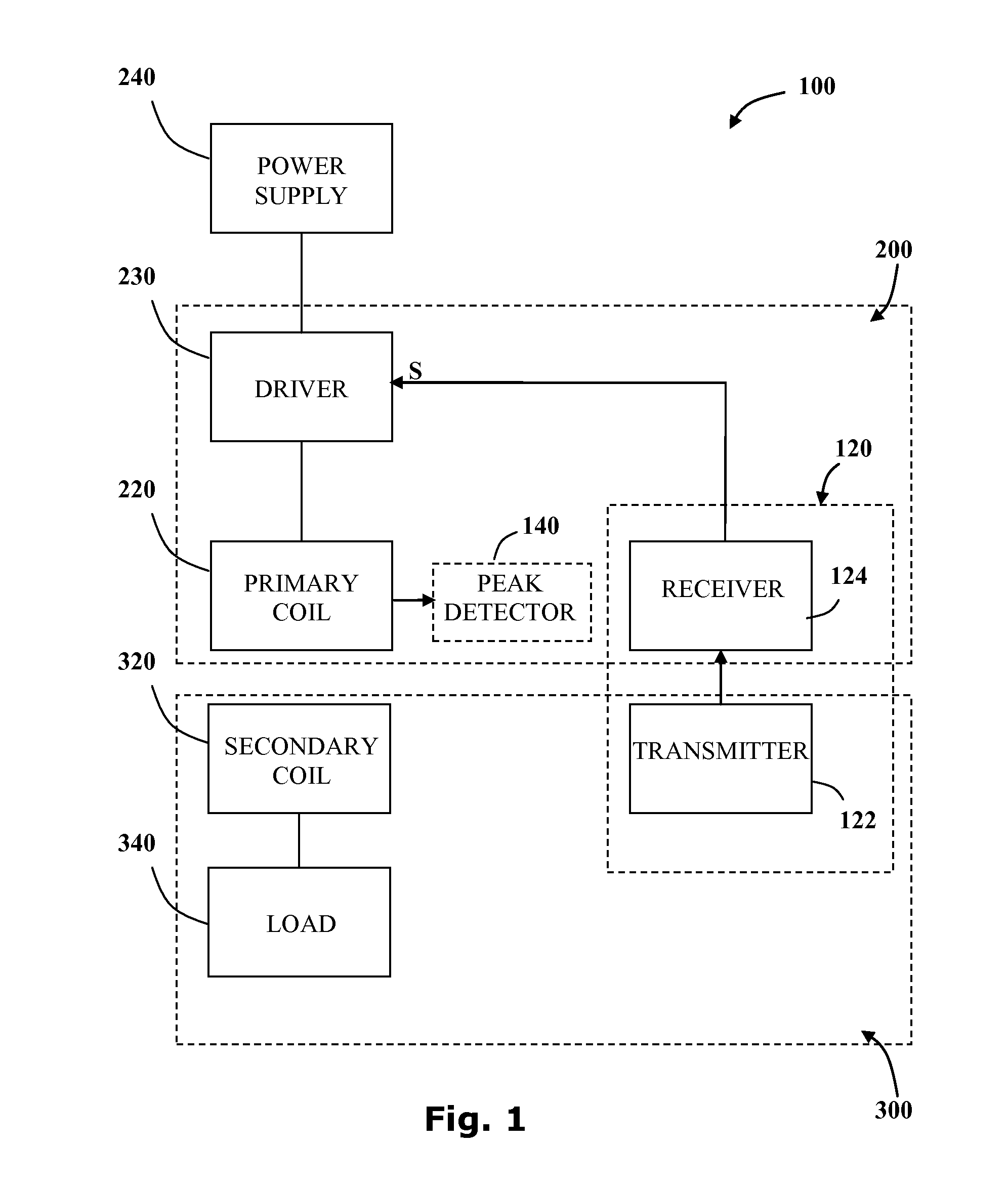
[0091]Reference is now made to FIG. 1 showing a block diagram of the main elements of an inductive power transfer system 100 adapted to transmit power at a non-resonant frequency according to another embodiment of the invention. The inductive power transfer system 100 consists of an inductive power outlet 200 configured to provide power to a remote secondary unit 300. The inductive power outlet 200 includes a primary inductive coil 220 wired to a power source 240 via a driver 230. The driver 230 is configured to provide an oscillating driving voltage to the primary inductive coil 220.

[0092]The secondary unit 300 includes a secondary inductive coil 320, wired to an electric load 340, which is inductively coupled to the primary inductive coil 220. The electric load 340 draws power from the power source 240. A communication channel 120 may be provided between a transmitter 122 associated with the secondary unit 300 and a receiver 124 associated with the inductive power outlet 200. The ...


PUM

PropertyMeasurementUnit
induced voltageaaaaaaaaaa
time durationaaaaaaaaaa

Abstract

An inductive power transfer system and method for transferring power to an electrical device wirelessly. The system includes an inductive power outlet and an inductive power receiver. During operation, instruction signals are sent from the inductive power outlet to the inductive power receiver. When no instruction signals are transferred, the system is configured to deactivate such that power is drawn by the system only during operation.

Description

CROSS-REFERENCE TO RELATED APPLICATIONS[0001]This application is a continuation-in-part of U.S. application Ser. No. 12 / 497,088 filed Jul. 2, 2009, which, in turn, claims the benefit of U.S. provisional applications No. 61 / 129,526 filed Jul. 2, 2008 and No. 61 / 129,859 filed Jul. 24, 2008, the disclosures of all of which are hereby incorporated by reference in their entirety.FIELD OF THE INVENTION[0002]The present invention is directed to providing energy efficient inductive power transfer. More specifically, the present invention relates to inductive power transfer systems and methods incorporating activation and termination mechanisms.BACKGROUND OF THE INVENTION[0003]The efficient use of available energy is of great importance for a number of reasons. On a global scale, there is increasing concern that the emission of greenhouse gases such as carbon dioxide from the burning of fossil fuels may precipitate global warming. Moreover, energy resources are limited. The scarcity of globa...

Claims


Application Information

Patent Timeline
Patent Type & Authority Applications(United States)
IPC IPC(8): H01F38/14
CPCY02B70/1433Y02B70/1441H02M3/3376H01F38/14H01F2038/143H02M2007/4815H02J17/00H02J5/005H04B5/0037H02J50/12H02J7/00045H02J7/0029H02J7/0047Y02B70/10H02M7/4815H02J50/80H02J50/40H04B5/0075
Inventor AZANCOT, YOSSIBEN-SHALOM, AMIRGREENWALD, OOLAROFE, ARIKLEIBOVITZ, ALFREDASHERY, MOTI
Owner POWERMAT TECHNOLOGIES
Why Eureka
Try Eureka