Core fixing member and coil device

Active Publication Date: 2012-08-02
TAMURA KK
View PDF9 Cites 39 Cited by
  • Summary
  • Abstract
  • Description
  • Claims
  • Application Information

AI Technical Summary

Benefits of technology

[0006]However, the stay disclosed in patent document #2 has a drawback that since an elastically deformable part (i.e., a part connecting the fixing part with the part of the core buried in the coating) is short, the rigidity is large and thereby it becomes impossible to sufficiently secure the vibration releasing effect by the elasticity of the spring. Fu

Problems solved by technology

However, the stay disclosed in patent document #2 has a drawback that since an elastically deformable part (i.e., a part connecting the fixing part with the part of the core buried in the coating) is short, the rigidity is large and thereby it becomes impossible to sufficiently secure the vibration releasing effect by the elasticity of the spring.
Furthermore, the number of components installed during the insert molding is large, and a high degree of installation accuracy is required.
Therefore, a set up process for the insert molding becomes complicated

Method used


Image

  • Core fixing member and coil device
  • Core fixing member and coil device
  • Core fixing member and coil device

Examples


Embodiment Construction

[0032]Hereinafter, an embodiment according to the invention are described with reference to the accompanying drawings.

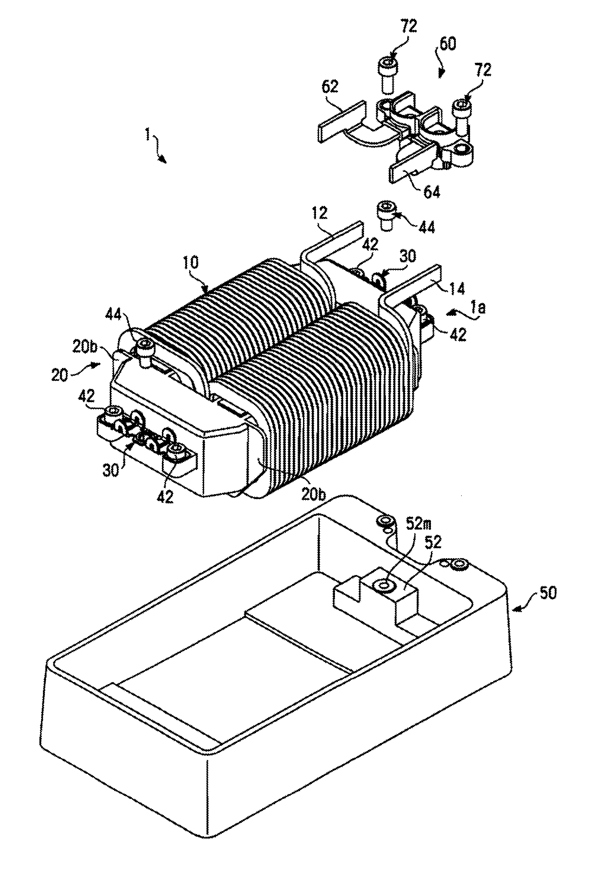
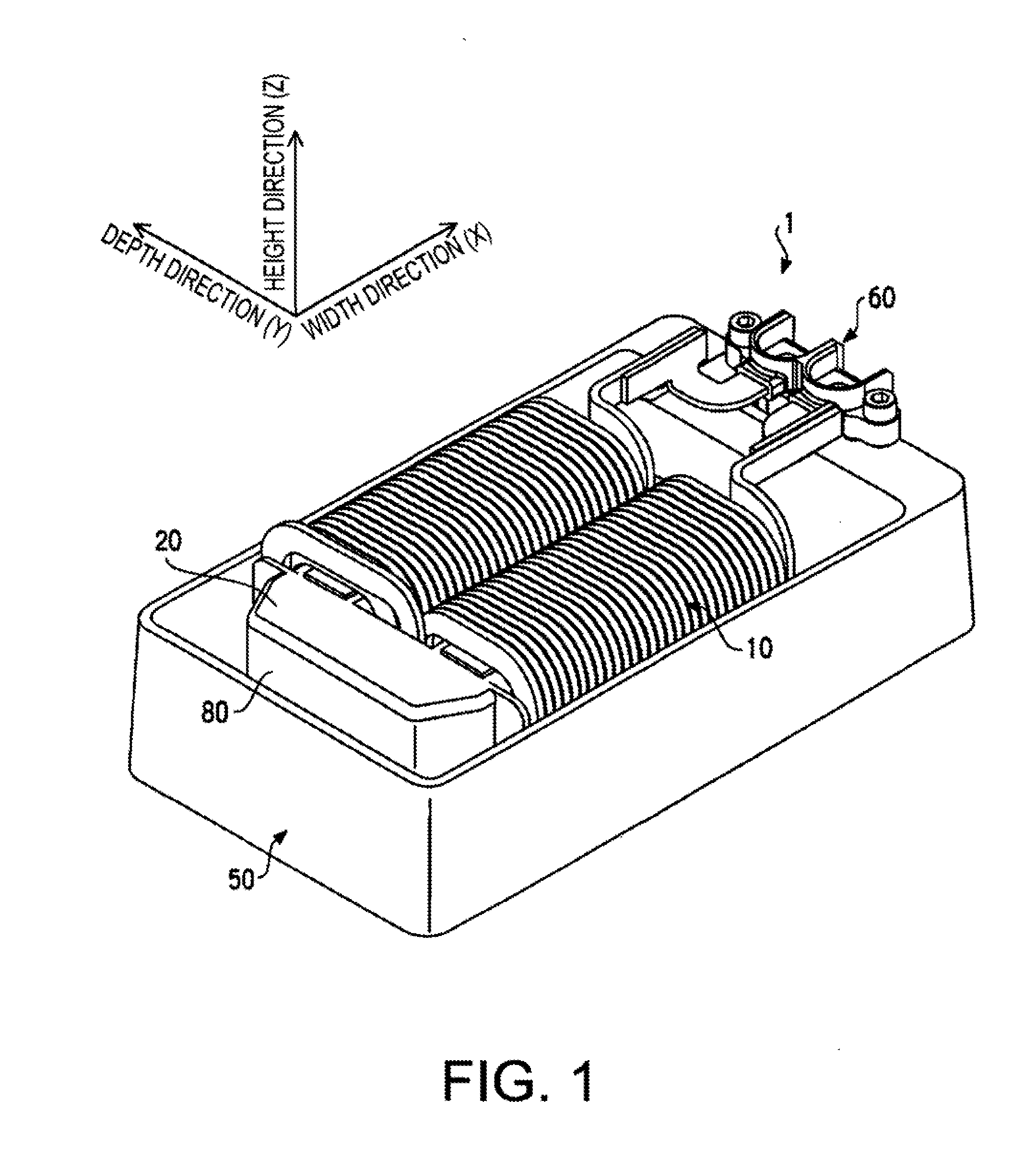
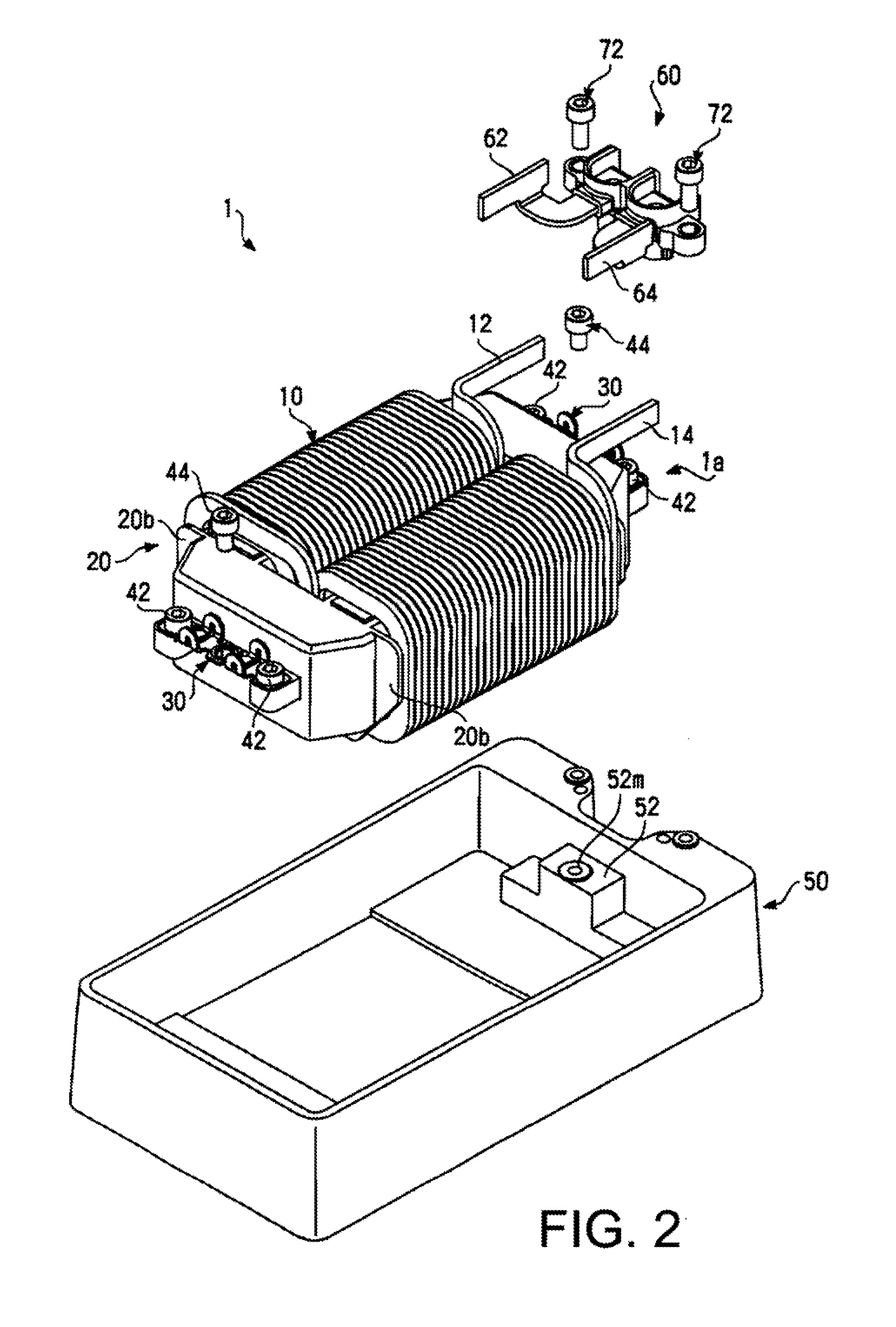
[0033]FIG. 1 is a perspective view of a reactor 1 according to the embodiment of the invention. FIG. 2 is an exploded view of the reactor 1. In the following, a direction pointing from the lower left part to the upper right part on FIG. 1 is defined as a width direction (X axis direction), a direction pointing from the lower right part to the upper left part on FIG. 1 is defined as a depth direction (Y axis direction), and a direction pointing from the lower side to the upper side is defined as a height direction (Z axis direction) for convenience of explanation. When the reactor 1 is used as a component in an apparatus, the reactor 1 may be oriented in any direction.

[0034]As shown in FIGS. 1 and 2, the reactor 1 includes a reactor body 1a having a coil 10 and a core 20, a radiation case 50, a core fixing member 30 and a terminal base 60. The reactor body 1a is accom...


PUM


Abstract

A core fixing member including: a core fixing part that has a plate-like shape and is to be fixed to a core; a case fixing part that has a plate-like shape and is to be fixed to a case; and at least one an arm part connecting the case fixing part with the core fixing part, and wherein the core fixing part and the case fixing part are arranged in a same plane, and the at least one arm part is formed in a shape of a letter ‘U’, and one end of the at least one arm part is connected to the core fixing part and the other end of the at least one arm part is connected to the case fixing part.

Description

BACKGROUND OF THE INVENTION[0001]The present invention relates to a coil device having a core, and a core fixing member for fixing a core to a case of the coil device.[0002]A reactor is a passive element which gives an inductive reactance to an alternating component of a signal, and is used, for example, in an inverter circuit, an active filer circuit or a DC step-up circuit. A reactor is also used for a DC step-up and step-down converter which is a key device of a driving system in a hybrid vehicle or an electric vehicle which has been brought in practical use in recent years. In general, a reactor having a relatively large capacity used for an electric vehicle is configured such that a core which is a magnetic material formed in a ring shape and a coil wound around the core are accommodated in a radiation case. In order to prevent magnetic saturation, in general, a structure (a divided core structure) in which the core is divided into a plurality of pieces arranged in a plane whic...

Claims


Application Information

Patent Timeline
IPC IPC(8): H01F27/06
CPCH01F27/266
Inventor SUZUKI, KOTARO
Owner TAMURA KK
Why Eureka
Try Eureka