Touch switch with 3D effect

A touch switch, 3D effect technology, used in electronic switches, adhesive types, polyurea/polyurethane adhesives, etc. Insufficient and other problems, to achieve the effect of improving service life and good installation accuracy

Pending Publication Date: 2021-12-28
浙江金池科技有限公司
View PDF0 Cites 0 Cited by
  • Summary
  • Abstract
  • Description
  • Claims
  • Application Information

AI Technical Summary

Problems solved by technology

[0006] In order to improve the situation that the membrane switch may have insufficient contact between the upper contact of the control circuit and the lower plate of the control circuit, thereby affecting the service life of the membrane switch, this application provides a touch switch with 3D effect

Method used


Image

  • Touch switch with 3D effect
  • Touch switch with 3D effect
  • Touch switch with 3D effect

Examples


preparation example 1

[0048] A hot-melt adhesive, made of the following raw materials in parts by weight: 300g poly-1,4-butylene adipate; 30g dimethylol propionic acid; 30g sodium ethylenediamine sulfonate; 100g iso Phorne diisocyanate; 50g hexamethylene diisocyanate; 20g1,4-butanediol; 50g acetone; 50g triethylamine;

[0049] Wherein polyadipate-1,4-butylene glycol ester is selected from West Asia Chemical Technology Co., Ltd. polyadipate-1,4-butylene glycol ester with a molecular weight of 2000; dimethylol propionic acid, isophor Ketone diisocyanate, hexamethylene diisocyanate, and 1,4-butanediol were all selected from Shanghai Jinjinle Industrial Co., Ltd.; sodium ethylenediaminoethanesulfonate was selected from Hubei Hongxin Ruiyu Fine Chemical Co., Ltd.;

[0050] A kind of preparation technology of hot-melt adhesive specifically comprises the following processing steps:

[0051] Step 1, adding 300g of polyadipate-1,4-butylene adipate with a molecular weight of 2000 in proportion to a three-ne...

preparation example 2-5

[0056] The difference between the proportioning parameters and process parameters of the raw materials in the preparation examples 2-5 and the preparation example 1 is recorded in Table 1, and the rest are the same as the preparation example 1.

[0057] Ratio parameters and process parameters of raw materials in table 1 preparation example 2-5 hot melt adhesive

[0058]

[0059]

preparation example 6

[0061] A heating agent, made of the following raw materials in parts by weight: 12g Al powder; 10g activated carbon;

[0062] A preparation process of exothermic agent specifically comprises the following process steps:

[0063] Take Al 2 o 3 Raw material, the Al 2 o 3 The raw materials were mechanically crushed and sieved with a 400-mesh sieve to obtain Al 2 o 3 powder, and then use hydrogen to Al 2 o 3 The powder undergoes hydrogenation reduction reaction to obtain Al powder with rough surface and spongy holes inside. Inert gas nitrogen is introduced into the Al powder, and then the particle size is added to the Al powder while maintaining the inert gas nitrogen. Activated carbon particles of 200 μm were filled with Al powder into the pores of the activated carbon particles to obtain a heat generating agent.


PUM

PropertyMeasurementUnit
Particle sizeaaaaaaaaaa

Abstract

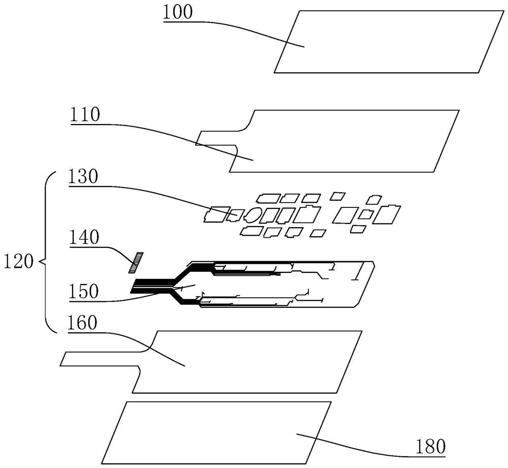
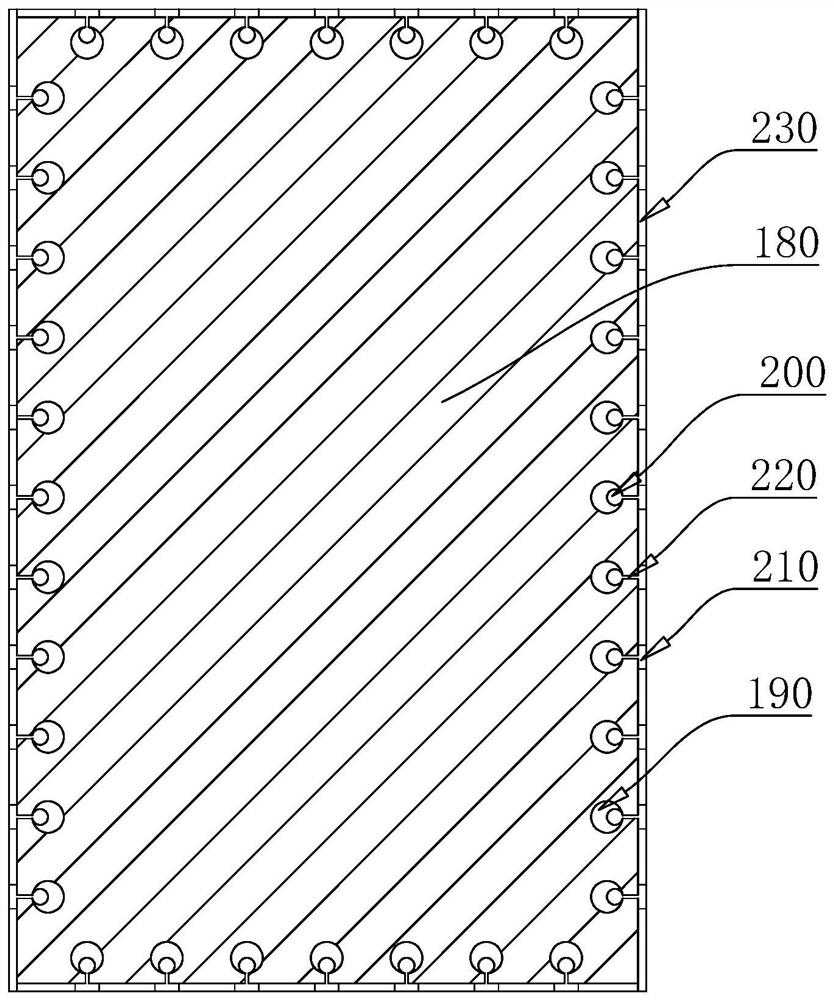
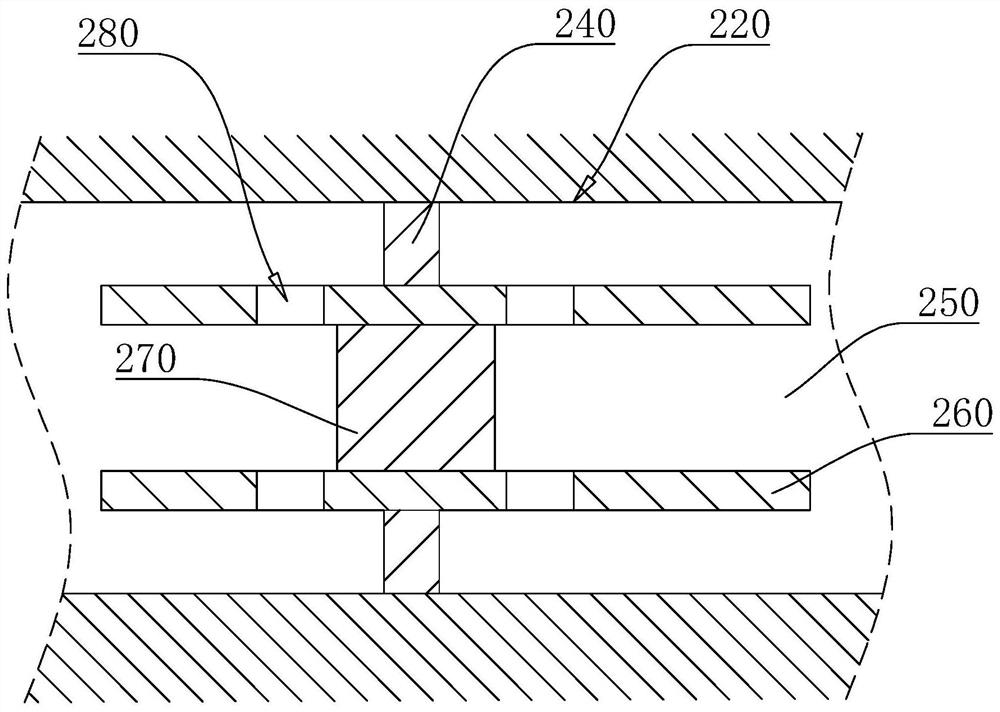
The invention relates to the technical field of thin film electronic devices, and particularly discloses a touch switch with a 3D effect. The touch switch with the 3D effect comprises a pattern layer, a base material and a touch switch circuit which are sequentially arranged, the touch switch circuit is sequentially provided with conductive oil, carbon paste, a silver paste circuit and a transparent insulating layer in the direction from the pattern layer to the base material, and the pattern layer or the transparent insulating layer is provided with an adhesive layer. According to the touch circuit, by adding the transparent insulating layer and the conductive oil, compared with an original mode that an upper-layer contact of the control circuit is in contact connection with a lower-layer polar plate of the control circuit, the situation that contact is insufficient after the contact and the polar plate are in contact for multiple times is avoided, the capacitive touch effect is achieved through the conductive oil, the touch circuit is controlled by changing the capacitance, and the service life of the touch switch can be prolonged to a certain extent.

Description

technical field [0001] This application relates to the technical field of thin film electronic devices, more specifically, it relates to a touch switch with 3D effect. Background technique [0002] Membrane switch is an operating system that integrates button functions, indicating elements, and instrument panels. It is made of several layers of films of different materials bonded into a finished product. The thickness is about 1.2-2.5mm, and it has the dual functions of the panel and the switch. Due to the short action stroke of the membrane switch, which is only about 0.25-0.5mm, and the switch pressing force is 0.5-1N, it is relatively sensitive, and the switch function is completed with a light touch of the hand, so it is also called a touch switch. The touch switch is well sealed, has the characteristics of moisture resistance and long service life, and is widely used in electronic measuring instruments, automobile industry, household appliances and other fields. [000...

Claims


Application Information

Patent Timeline
IPC IPC(8): H03K17/96C09J175/06C08G18/75C08G18/73C08G18/66C08G18/34C08G18/32C08G18/42C08J5/18C08L5/00C08L89/00C08K5/053
CPCH03K17/962C09J175/06C08G18/755C08G18/73C08G18/722C08G18/348C08G18/3857C08G18/3206C08G18/6659C08G18/4238C08J5/18C08J2305/00C08J2489/00C08J2389/00C08J2405/00C08K5/053
Inventor 凌舞金林升
Owner 浙江金池科技有限公司
Why Eureka
Try Eureka