Methods and systems for fiber delivery of high peak power optical pulses

a fiber and optical pulse technology, applied in the direction of electrical equipment, basic electric elements, laser details, etc., can solve the problems of reducing the quality of pulses, reducing the available energy of soliton pulses, and reducing the efficiency of soliton pulses, so as to achieve superior pulse quality for the end-use apparatus

Inactive Publication Date: 2012-08-02
IMRA AMERICA
View PDF4 Cites 16 Cited by
  • Summary
  • Abstract
  • Description
  • Claims
  • Application Information

AI Technical Summary

Benefits of technology

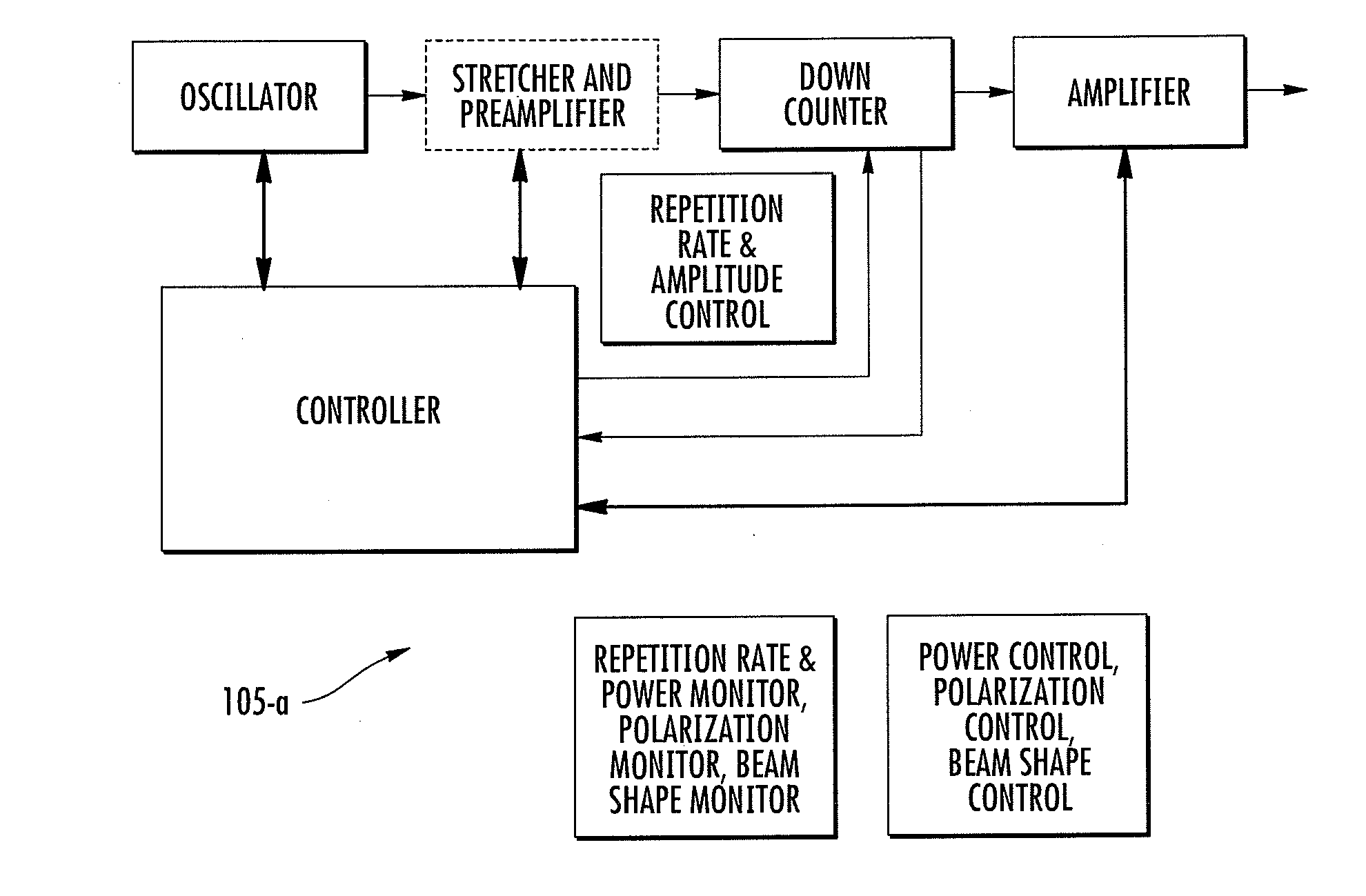
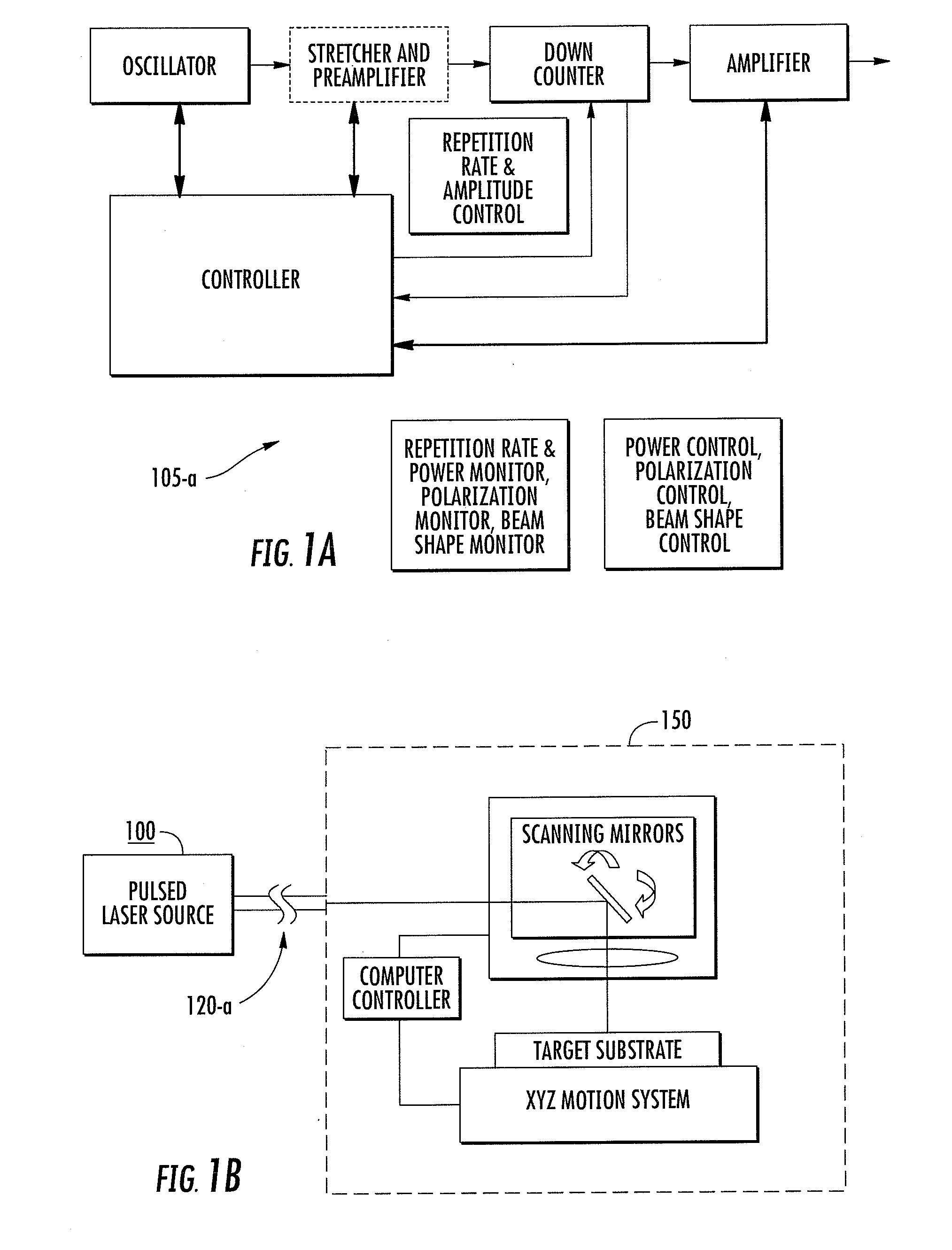
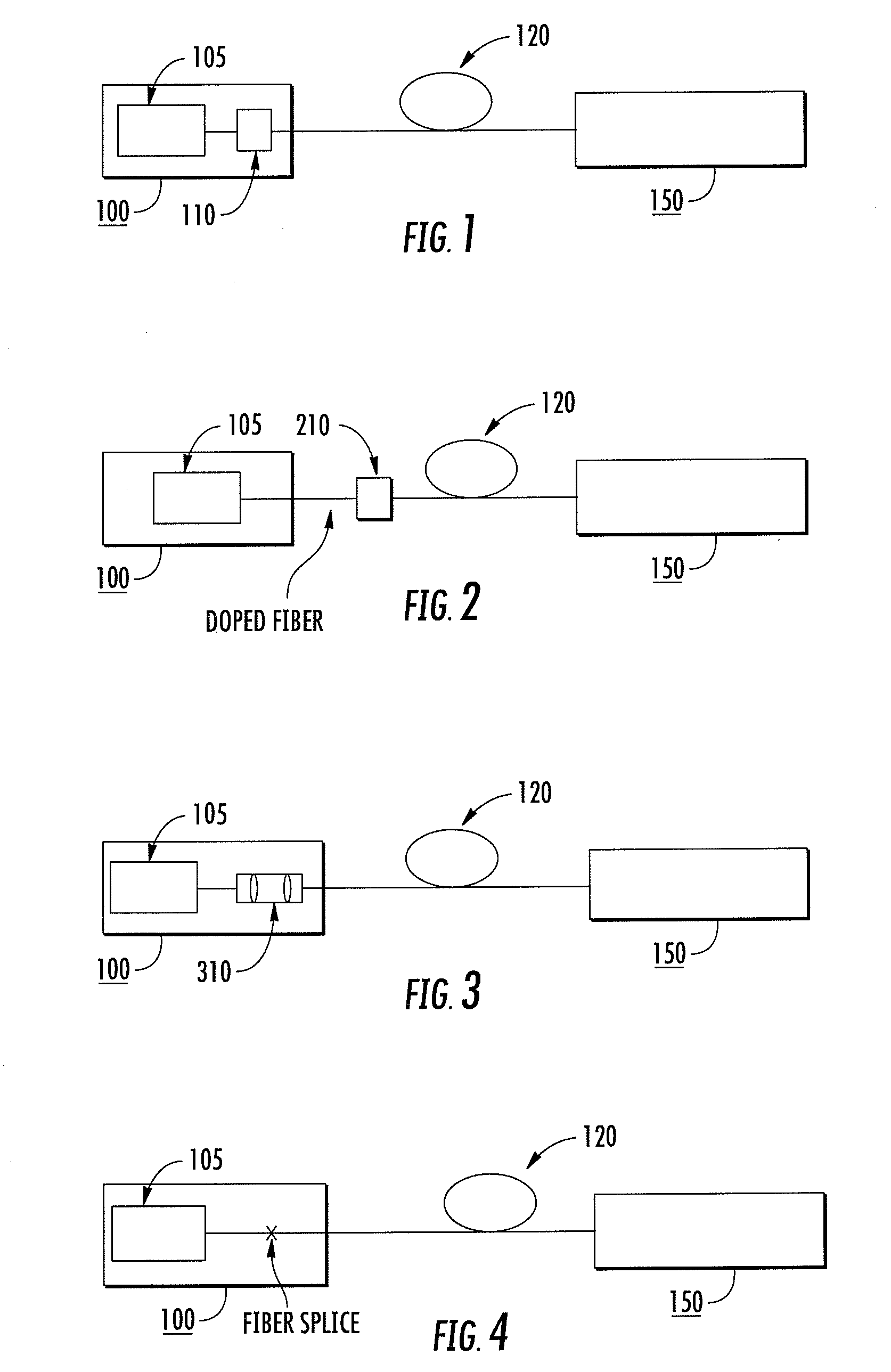
[0007]At least one embodiment includes stimulated Raman soliton (RS) generation in a delivery fiber disposed between a pulse source and an end use apparatus. High peak power pulses are delivered to the end use apparatus without significant deterioration in the shape of a pulse received from the pulse source. Furthermore, the quality of pulses delivered to an end use apparatus may be superior to that of pulses subjected to dispersion or other non-linear effects.
[0008]At least one embodiment provides for delivery of high peak power pulses from a remote laser source to an end use apparatus without a requirement for pulse stretching and compressing to avoid non-linear effects. In various embodiments RS generation is exploited to provide high quality, compressed pulses for the end use apparatus.
[0010]The signal loss within a typical range suitable for a delivery fiber, for example 100 m or less, is negligible if the fiber is undoped. Importantly, a doped gain fiber is not necessary for the RS optical pulse, which can be advantageous for a delivery fiber.

Problems solved by technology

In contrast to the delivery of continuous wave outputs or long pulses, nonlinear interaction of a high peak power pulse in an optical fiber can cause degradation of pulse quality.
Delivering high peak intensity optical pulses can be particularly difficult if such pulses are subjected to unwanted non-linear effects.
However, it can be shown that the available energy of soliton pulses is limited to not more than a few tens of picoJoules (pJ) in conventional optical fibers.
Pulse distortion occurs in either case.

Method used


Image

  • Methods and systems for fiber delivery of high peak power optical pulses
  • Methods and systems for fiber delivery of high peak power optical pulses
  • Methods and systems for fiber delivery of high peak power optical pulses

Examples


Embodiment Construction

[0029]Although it is not necessary to the practice of embodiments of the disclosed systems and methods to understand the underlying operative mechanisms, and without subscribing to any particular theory, it is useful to review various principles associated with Raman generation, and more particularly Raman solitons (RS),

[0030]Research in femtosecond pulse compression revealed that Raman scattering can improve the quality of compressed pulses in soliton-effect compressors (See G. P. Agrawal, Applications of non-linear fiber optics, Academic Press, pp. 280-287, (2001). Under certain optical conditions the propagation properties of RS in an optical fiber are similar to that of non-Raman solitons. To enter the RS regime, the fundamental pulse initially must reach the threshold intensity for stimulated Raman scattering given by:

gRPthLeffAeff≈16,

where gR is the Raman gain (on the order of 10−13 m / W), Pth is the threshold, Leff is the effective length and Aeff is the mode area.(See G. P. A...


PUM


Abstract

Methods and systems for delivery of high peak power optical pulses through optical fiber are disclosed. Raman soliton generation is utilized to maintain the properties of the pulses in the delivery fiber. The apparatus can comprise any high peak power pulse source and delivery fiber supporting Raman soliton generation.

Description

FIELD OF THE INVENTION[0001]The present invention relates to an apparatus and method for delivery of high peak power optical pulses through an optical fiber.BACKGROUND[0002]Delivery of high peak power optical pulses from a pulsed laser source to an end use apparatus through optical fiber is desirable in many laser based applications. By way of example, U.S. Pat. No. 6,249,630, entitled “Apparatus and method for delivery of dispersion-compensated ultrashort optical pulses with high peak power” and U.S. Pat. No. 6,320,191, entitled “Dispersive precompensator for use in an electromagnetic radiation generation and detection system” disclose fiber based delivery of high power ultrashort pulses and THz radiation, respectively.[0003]In contrast to the delivery of continuous wave outputs or long pulses, nonlinear interaction of a high peak power pulse in an optical fiber can cause degradation of pulse quality. Delivering high peak intensity optical pulses can be particularly difficult if su...

Claims


Application Information

Patent Timeline
Patent Type & Authority Applications(United States)
IPC IPC(8): H01S3/30
CPCH01S3/0057H01S3/06712H01S3/06741H01S2301/085H01S3/1301H01S3/2308H01S3/302H01S3/06754
Inventor CHO, GYU CHEONXU, JINGZHOU
Owner IMRA AMERICA
Why Eureka
Try Eureka