Optical connector adapter with shutter

a technology of optical connectors and shutters, applied in the field of optical connector adapters, can solve the problems of large number of parts such as the engaging piece and the stopper, the eye of an operator may be exposed to laser light leaked out of the adapter, and the difficulty of press molding, so as to achieve smooth insertion into the insertion hole, ensure the fixation, and ensure the effect of insertion

Active Publication Date: 2012-08-02
SEIKOH GIKEN
View PDF4 Cites 27 Cited by
  • Summary
  • Abstract
  • Description
  • Claims
  • Application Information

AI Technical Summary

Benefits of technology

[0019]According to an optical connector adapter according to the present invention, a shutter member is formed of a base plate, both side plates extending upward from both side edges of the base plate, a connecting plate extending upward from a front edge of the base plate, and a shutter plate connected to the connecting plate and curved with a predetermined curvature radius. Thus, the number of parts of the shutter member is small and even when the shutter member is produced by press molding, the level of difficulty of processing is low so that the shutter member in the same shape and size can be mass-produced in a short time by press molding. The shutter member can be produced at low production costs and therefore, the adapter itself can be produced at low unit costs. The shutter member can easily be mounted on the adapter by fitting the base plate of the shutter member into a bottom recess formed on an external surface of a bottom wall of the adapter and fitting the both side plates of the shutter member into both side recesses formed on the external surface of both sidewalls of the adapter and therefore, mounting of the shutter member on the adapter is easy and the adapter can be assembled without much expense in time and effort and, as a result, the adapter itself can be produced at low unit costs. When the shutter member is mounted on the adapter, outside dimensions of the adapter do not become too large so that the adapter can be contained within the standard outside dimensions. If an optical connector plug is inserted through an end of an insertion hole of the adapter, the shutter plate of the shutter member falls toward a center portion of the insertion hole by being pressed by the optical connector plug and therefore, shielding by the shutter plate can be released and an optical signal can be connected. If the optical connector plug is extracted from the insertion hole, the shutter plate rises owing to an elastic force thereof to shield the insertion hole again so that leakage of laser light from the adapter can reliably be prevented.
[0027]In an optical connector adapter in which the thickness dimension of the shutter plate is in the range of 0.01 to 0.1 mm and the elastic / repulsive force of the shutter plate is in the range of 0.1 to 0.6 N, the thickness dimension of the shutter plate is in the above range and therefore, the shutter member of the same shape and size can be mass-produced in a short time by press molding so that the shutter member can be produced at low production costs and. As a result, the adapter itself can be produced at low unit costs. The elastic / repulsive force of the shutter plate is in the above range and thus, when the optical connector plug is inserted through the end of the insertion hole, the shutter plate of the shutter member reliably falls toward the center portion of the insertion hole and therefore, shielding by the shutter plate can reliably be released. When the optical connector plug is extracted from the insertion hole, the shutter plate reliably rises due to the elastic force thereof and thus, the insertion hole can reliably be shielded.

Problems solved by technology

If removal work of the optical connector plug inserted into the adapter is done while laser light being oscillated from the optical oscillating apparatus, there is a danger that eyes of an operator may be exposed to laser light leaked out from the adapter.
While the shutter metal fitting used for the adapter is produced by press molding, the number of parts such as the engaging piece and the stopper is large and the level of difficulty of press molding is high to increase the accuracy of such parts.
Further, after the shutter metal fitting is created by press molding, it is necessary to assemble into a hollow prismatic shape and thus, not only efforts and time for the assembly, but also production costs of the shutter metal fitting are needed and, as a result, unit costs of the adapter itself rise.

Method used


Image

  • Optical connector adapter with shutter
  • Optical connector adapter with shutter
  • Optical connector adapter with shutter

Examples


Embodiment Construction

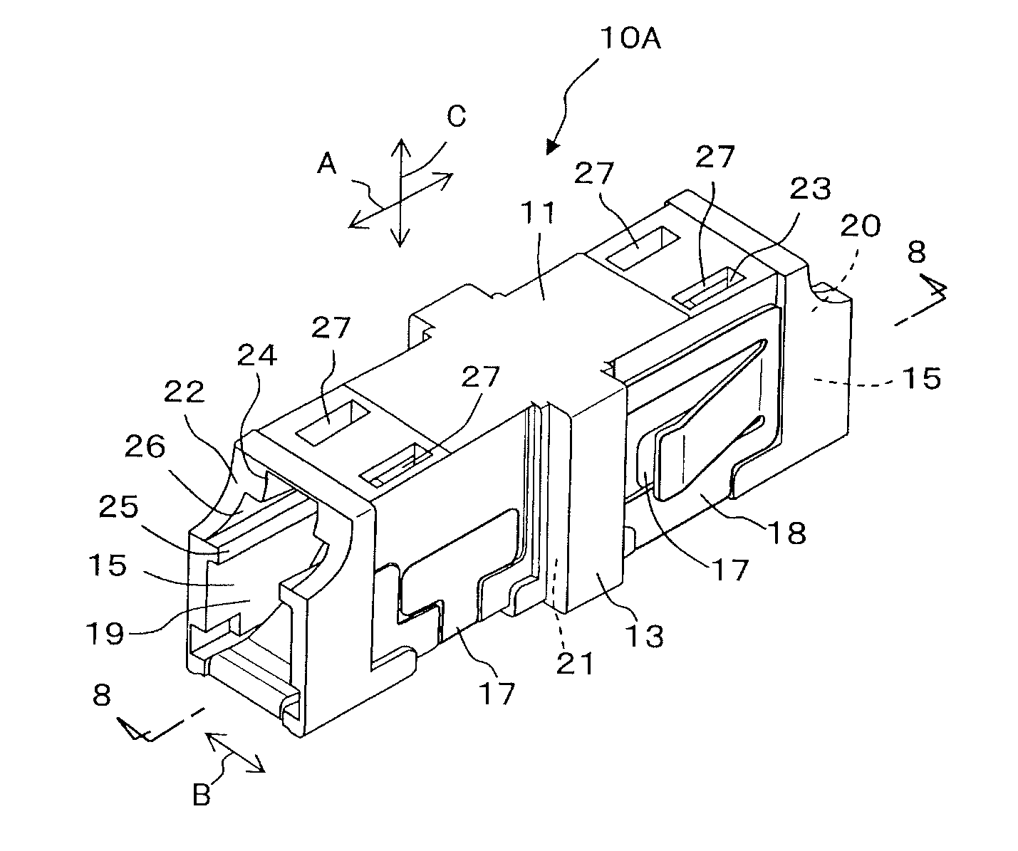
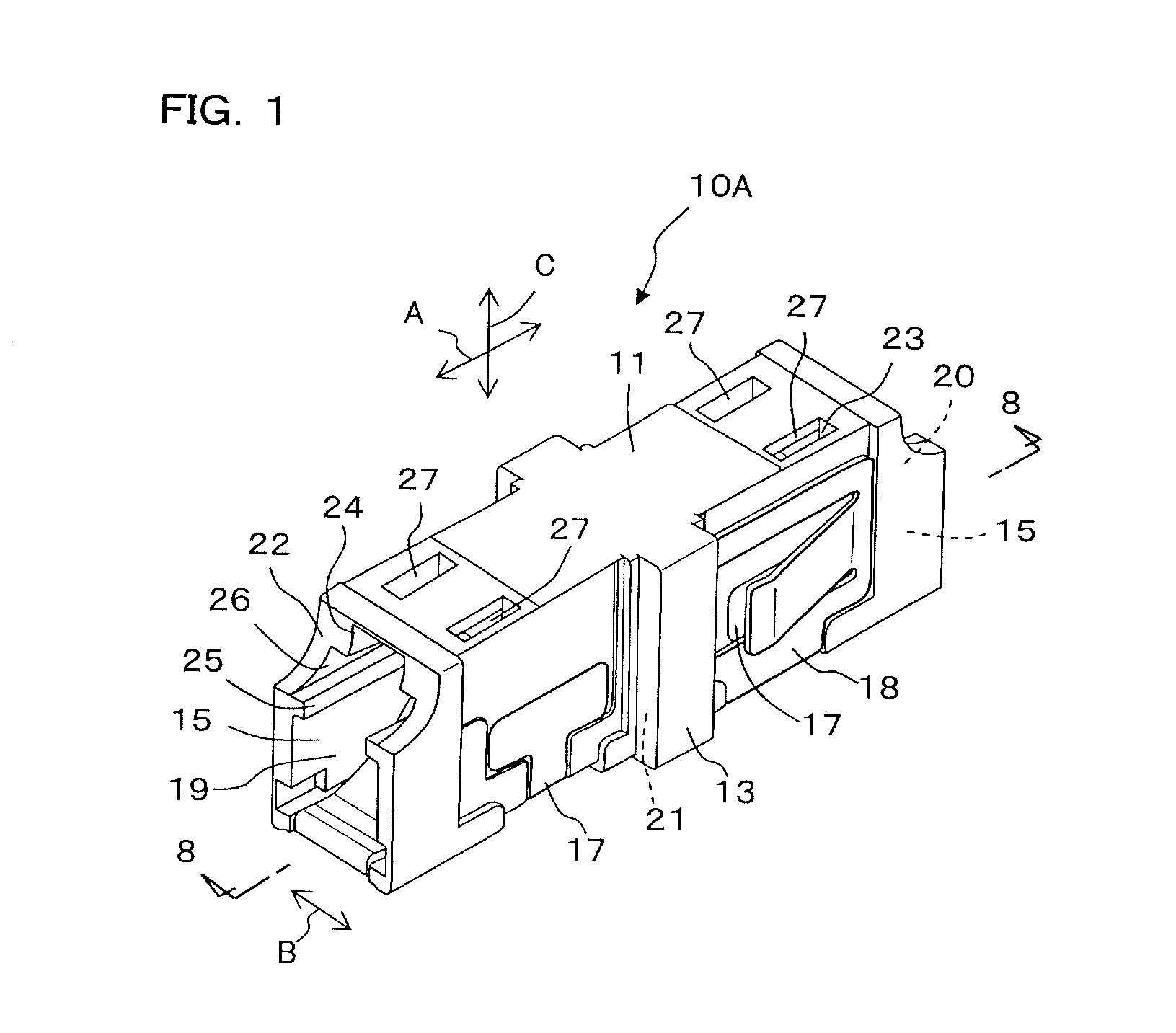
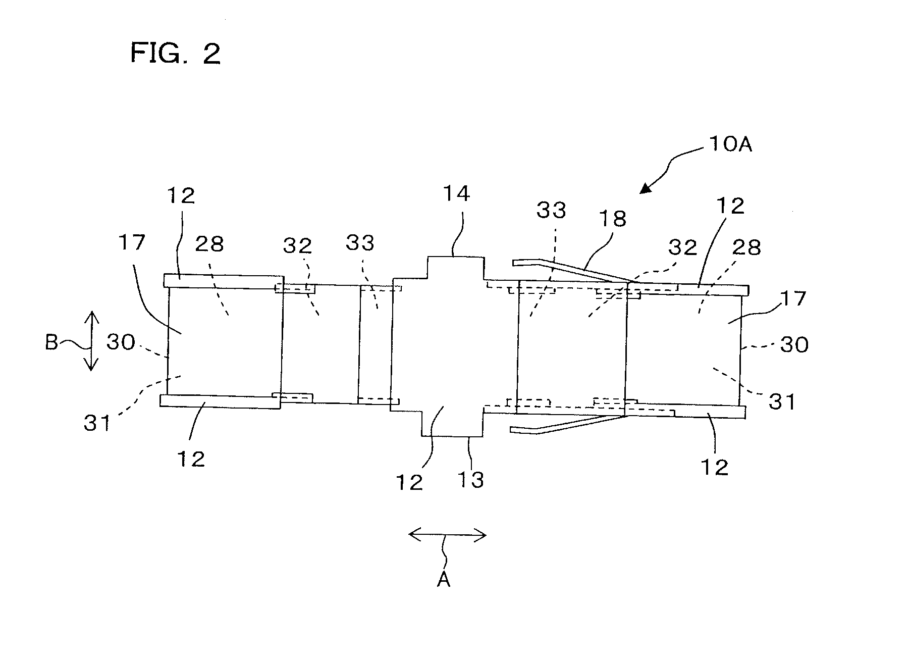
[0048]Details of an optical connector adapter according to the present invention will be described as shown below with reference to appended drawings such as FIG. 1 as a perspective view of an optical connector adapter shown as an example. FIG. 2 is a bottom view showing a bottom wall 12 of an adapter 10A and FIG. 3 is a side view showing a sidewall 13 of the adapter 10A. FIG. 4 is a bottom view showing the bottom wall 12 of the adapter 10A before a shutter member 17 (shielding metal fitting) and a stopper member 18 (locking metal fitting) are mounted and FIG. 5 is a side view showing the sidewall 13 of the adapter 10A before the shutter member 17 and the stopper member 18 are mounted. FIG. 6 is a perspective view of the shutter member 17 shown as an example and FIG. 7 is a perspective view of the stopper member 18 shown as an example. FIG. 8 is a sectional view on an 8-8 line arrow of FIG. 1. In FIGS. 1 to 3, 6, and 7, the front-back direction is indicated by an arrow A, a lateral ...


PUM


Abstract

An optical connector adapter with shutter having a fewer number of parts and a shutter member that can easily be produced is provided.The shutter member of the optical connector adapter with shutter includes a base plate, both side plates, a connecting plate, and an elastically deformable shutter plate having a predetermined curvature radius. In the adapter, the base plate of the shutter member is fitted into a bottom recess formed on an external surface of a bottom wall and the both side plates of the shutter member are fitted into both side recesses formed on the external surface of both sidewalls. The shutter plate of the shutter member is positioned at both open ends of an insertion hole to shield the insertion hole while being curved to form a convex shape toward a center portion of the insertion hole and, when a optical connector plug is inserted into the insertion hole, falls toward the center portion of the insertion hole by being pressed by the optical connector plug.

Description

BACKGROUND OF THE INVENTION[0001]1. Field of the Invention[0002]The present invention relates to an optical connector adapter that connects optical connector plugs or an optical connector plug and an optical oscillating apparatus such as a semiconductor laser.[0003]2. Description of the Related Art[0004]In optical communication in which laser light oscillated from an optical oscillating apparatus such as a semiconductor laser is transmitted by using an optical fiber, an optical connector adapter that allows an optical connector plug to be removably inserted is used as a unit for connecting the optical fiber. If removal work of the optical connector plug inserted into the adapter is done while laser light being oscillated from the optical oscillating apparatus, there is a danger that eyes of an operator may be exposed to laser light leaked out from the adapter.[0005]To avoid such a danger, an optical connector adapter including a housing formed of top / bottom walls and both sidewalls,...

Claims


Application Information

Patent Timeline
Patent Type & Authority Applications(United States)
IPC IPC(8): G02B6/38
CPCG02B6/3825G02B6/3874G02B6/3849
Inventor JIBIKI, MASAYUKITAIRA, JUNJI
Owner SEIKOH GIKEN
Why Eureka
Try Eureka