System and method for producing carbon nanotubes

Active Publication Date: 2012-08-02
MCD TECH SARL
View PDF1 Cites 8 Cited by
  • Summary
  • Abstract
  • Description
  • Claims
  • Application Information

AI Technical Summary

Benefits of technology

[0012]Disclosed herein is a process of catalyst preparation and synthesis of nanotubes and apparatus for synthesis of nanotubes. In the methods disclosed herein, the catalyst preparation and nanotube synthesis is realized simultaneously in a single apparatus as disclosed herein. The methods and appa

Problems solved by technology

The main limitations of the arc discharge method, however is low nanotube yield, typically no more than about 25% to 30% by weight of total carbon mass, the relatively small size of the nanotubes produced (typically having lengths of up to about 50 to 1000 nanometers, difficulties associated with separating out the nanotubes in a pure form, and difficulties with varying diameter and length dimensions of the nanotubes formed by this process.
However, despite these advantages, present catalytic synthesis methods of carbon nanotubes synthesis are high cost, which is driven by large volume of catalyst usage and low yield of carbon nanotubes per un

Method used


Image

  • System and method for producing carbon nanotubes
  • System and method for producing carbon nanotubes
  • System and method for producing carbon nanotubes

Examples


example 1

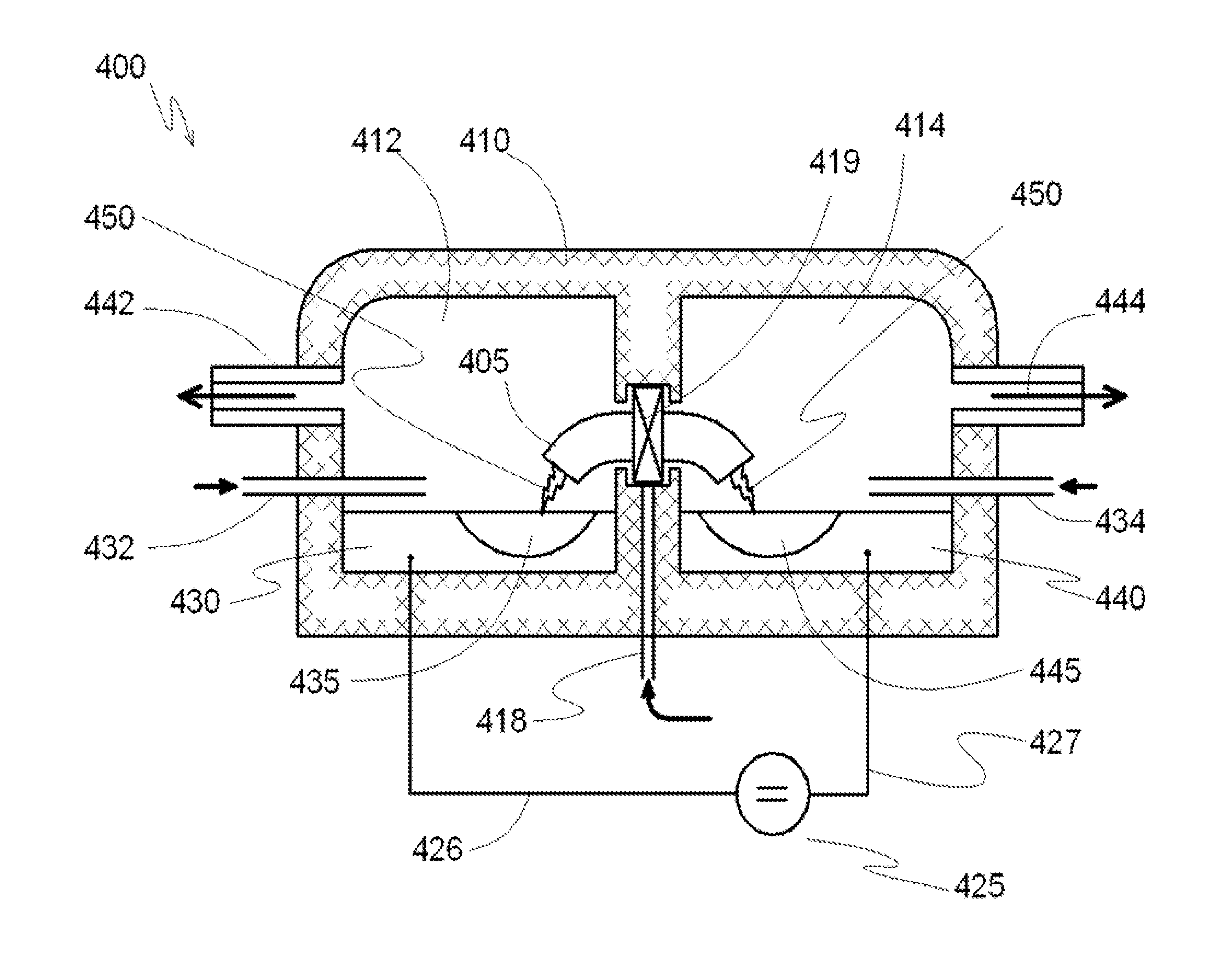
[0076]In a reactor system for producing carbon nanotubes containing two separate reaction chambers 412 and 414 connected by a discharge channel 405, for example as described with reference to FIG. 4 is provided, wherein the volume of each reaction chamber is about 5 m3. At the bottom of each reaction chamber 412 and 414 reservoirs are formed which are open in the volume of the respective reaction chambers. The reservoirs are lined with refractory bricks and completely filled with a catalyst comprising monolithic iron forming electrodes 430 and 440. The volume of each reservoir is about 50 liters, and each is equipped with a conductor for supplying electrical voltage directly to the metal catalyst electrodes 430 and 440. Each reaction chamber 412 and 414 has a respective inlet port 432 and 434 for introducing gaseous hydrocarbons into the reactor chambers and a respective outlet port 442 and 444 for extracting the reaction products from each respective reaction chamber.

[0077]The disc...

example 2

[0081]The reactor has three chambers, as shown in FIG. 6. Inside, each reaction chamber is lined with fire-resistant bricks. The first reaction chamber, which has a volume of about 1 M3, and the second reaction chamber, which has a volume of about 2 M3, are connected by a discharge channel and a gas pipe. The second reaction chamber is connected to the third reaction chamber (which has a volume of about 7 M3) by a gas pipe. First reaction chamber has a chamber for supplying gaseous carbohydrates. The third reaction chamber has a channel for outflow of gas from the reaction chamber. The first and second reaction chambers have electrodes that include a catalyst—monolithic iron. The volume of each reservoir is about 50 liters. Each reservoir has a conductor to supply the voltage directly to the metal. The reservoirs with the metal function as electrodes.

[0082]The discharge channel that connects the first and second chambers is in the form of a symmetrical arc. Each cross-section of the...

example 3

[0085]The reactor for manufacturing of carbon nanotubes includes three sequentially arranged reaction chambers, as shown in FIG. 6. Inside, each reaction chamber is lined with fire resistant brick. The first reaction chamber (in order from right to left) has a volume of 0.4 m3, and the second reaction chamber, which has a volume of 0.6 m3, are connected to each other by a discharge channel and a gas pipe. The second reaction chamber is connected to the third reaction chamber, which has a volume of 1 m3, by a gas pipe. Each chamber includes channel / ports for supplying of gaseous carbohydrates. The third reaction chamber has a channel for pumping out the gas from the reaction chamber volume. In the bottom of the first and second reaction chambers there are reservoirs, which are open into the volume of their corresponding reaction chambers, lined with fire resistant brick, and fully filled with a catalyst—monolithic iron. The volume of each reservoir is 50 liters.

[0086]Each reservoir i...


PUM


Abstract

A method of producing carbon nanotubes, comprising, in a reaction chamber: evaporating at least a partially melted electrode comprising a catalyst by an electrical arc discharge; condensing the evaporated catalyst vapors to form nanoparticles comprising the catalyst; and decomposing gaseous hydrocarbons in the presence of the nanoparticles to form carbon nanotubes on the surface of the nanoparticles. Also a system for producing carbon nanotubes, comprising: a reactor comprising two electrodes, wherein at least one of the electrodes is at least a partially melted electrode comprising a catalyst, the reactor adapted for evaporating the at least partially melted electrode by an electrical arc discharge and for condensing its vapors to form nanoparticles comprising the catalyst, wherein the electrodes are disposed in a reaction chamber for decomposing gaseous hydrocarbons in the presence of the nanoparticles to form carbon nanotubes on the surface of the nanoparticles.

Description

TECHNICAL FIELD[0001]The present invention relates to methods and systems for synthesizing carbon nanotubes, and, in particular, to methods and systems for catalytic synthesis of carbon nanotubes.[0002]The invention has been developed primarily for use in efficient nanotubes synthesis using catalytic hydrocarbon decomposition inside a reaction chamber of a reactor with high yield and will be described hereinafter with reference to this application. However, it will be appreciated that the invention is not limited to this particular field of use or application.BACKGROUND OF THE RELATED ART[0003]Any discussion of the background art throughout the specification should in no way be considered as an admission that such background art is prior art, nor that such background art is widely known or forms part of the common general knowledge in the field.[0004]Carbon nanotubes, an allotrope of carbon with a cylindrical nanostructure, have attracted a considerable amount of interest recently d...

Claims


Application Information

Patent Timeline
IPC IPC(8): D01F9/127D01F9/133B01J19/08B82Y30/00B82Y40/00
CPCB82Y30/00C01B31/0226B82Y40/00C01B32/16
Inventor PREDTECHENSKY, MIKHAIL RUDOLFOVICHTUKHTO, OLEG MIKHAILOVICHKOVAL, ILYA YURIEVICH
Owner MCD TECH SARL
Why Eureka
Try Eureka