Cylindrical burner and method for making the same

a cylindrical burner and cylindrical technology, applied in the field of cylindrical burners, can solve the problems of lack of flexibility for making different geometric shapes required for some burners, lack of longevity in many applications, and high cost of gas burner manufacturing, and achieve the effect of low thermal expansion material

Inactive Publication Date: 2012-08-02
APOGEE ENGINEERED CERAMICS
View PDF6 Cites 15 Cited by
  • Summary
  • Abstract
  • Description
  • Claims
  • Application Information

AI Technical Summary

Benefits of technology

[0021]One advantage of the present invention may be that it provides for an improved gas burner.
[0022]A further advantage of the present invention may be that it provides for an improved ceramic gas burner capable of being manufactured into geometrical shapes.
[0023]Still a further advantage of the present invention may be that it provides for a ceramic gas burner that can be used as both an atmospheric and a powered gas burner depending on the application and use for the gas burner.
[0024]Yet a further advantage of the present invention may be that it provides a solid ceramic perforated tube having a flange and an end cap to act as a cylindrical burner for a burner with turndown characteristics in the range of 30 to 1.
[0025]Yet another advantage of the present invention may be that a cap may be arranged on the end of the tube of the burner in a preformed manner or as an extra component to the top of the tube once assembly occurs.
[0026]Yet another advantage of the present invention may be that it provides for a gas burner that has a material composition with an extremely low thermal expansion material with a high percentage of open porosity to allow for infrared radiant properties at the lower BTU input ranges.

Problems solved by technology

In many cases ceramics provide the ideal thermal properties for gas burner applications, however, they may lack the flexibility for making different geometrical shapes required for some burners such as cylindrical, concave, convex, conical, domed or any other difficult to manufacture shapes.
Some of the high temperature alloy metals used in gas burners are more flexible but have high heat conductivity, and are subject to degrading from the extreme temperatures of burners and lack longevity in many of the applications that the commercial and residential users need.
However, many of these prior art gas burners are expensive to manufacture, use expensive materials and often require substrates to support the material which adds to the complexity and cost to manufacture such products.
Furthermore, many of these prior art gas burners have limitations that reduce there effectiveness and competitiveness in a cost conscience environment.
Some of these prior art burners have limited turn down capabilities, while others which are made of reticulated ceramic structure (or ceramic foam), have inconsistence openings resulting in inconsistence burning patter.
Furthermore, these burners are fragile and develop hairline cracks over time which results in claps of the burner structure.
Furthermore, some of these prior art woven ceramic fiber burners may have a limited turn down capability and seem to be fragile and not as robust as the applications require.
Also, many of these prior arts gas burners are not efficient, produce too much pollution and are extremely complicated and expensive to manufacture.
Furthermore, many of these prior heating systems require a high level of automation capital costs to produce one unit.
These restrictions on the prior art burners do not allow the practical means for manufacturing and impedes the widespread use of these more efficient designs.

Method used


Image

  • Cylindrical burner and method for making the same
  • Cylindrical burner and method for making the same
  • Cylindrical burner and method for making the same

Examples


Embodiment Construction

)

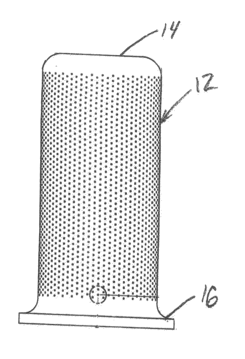
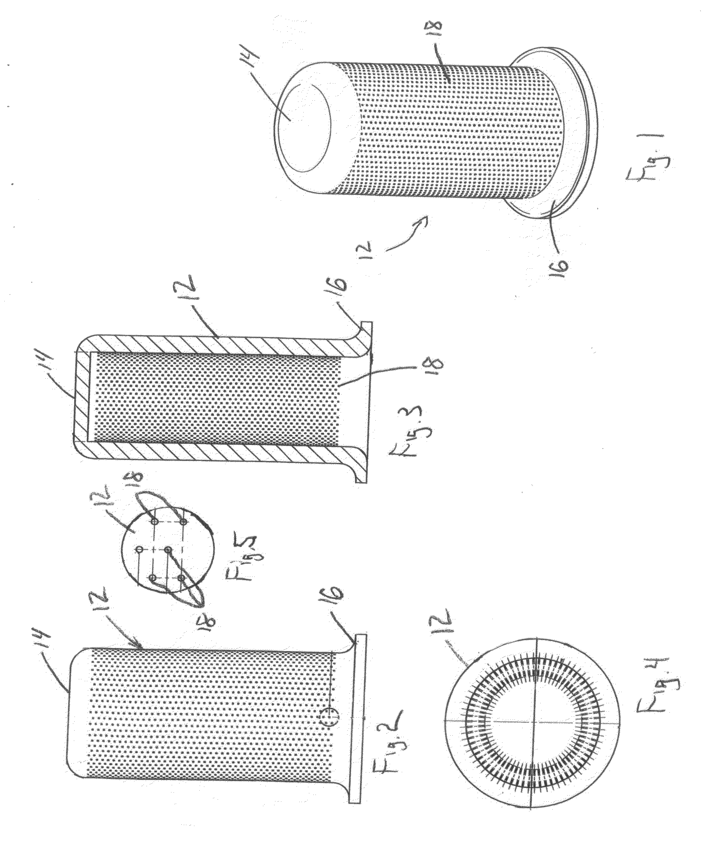
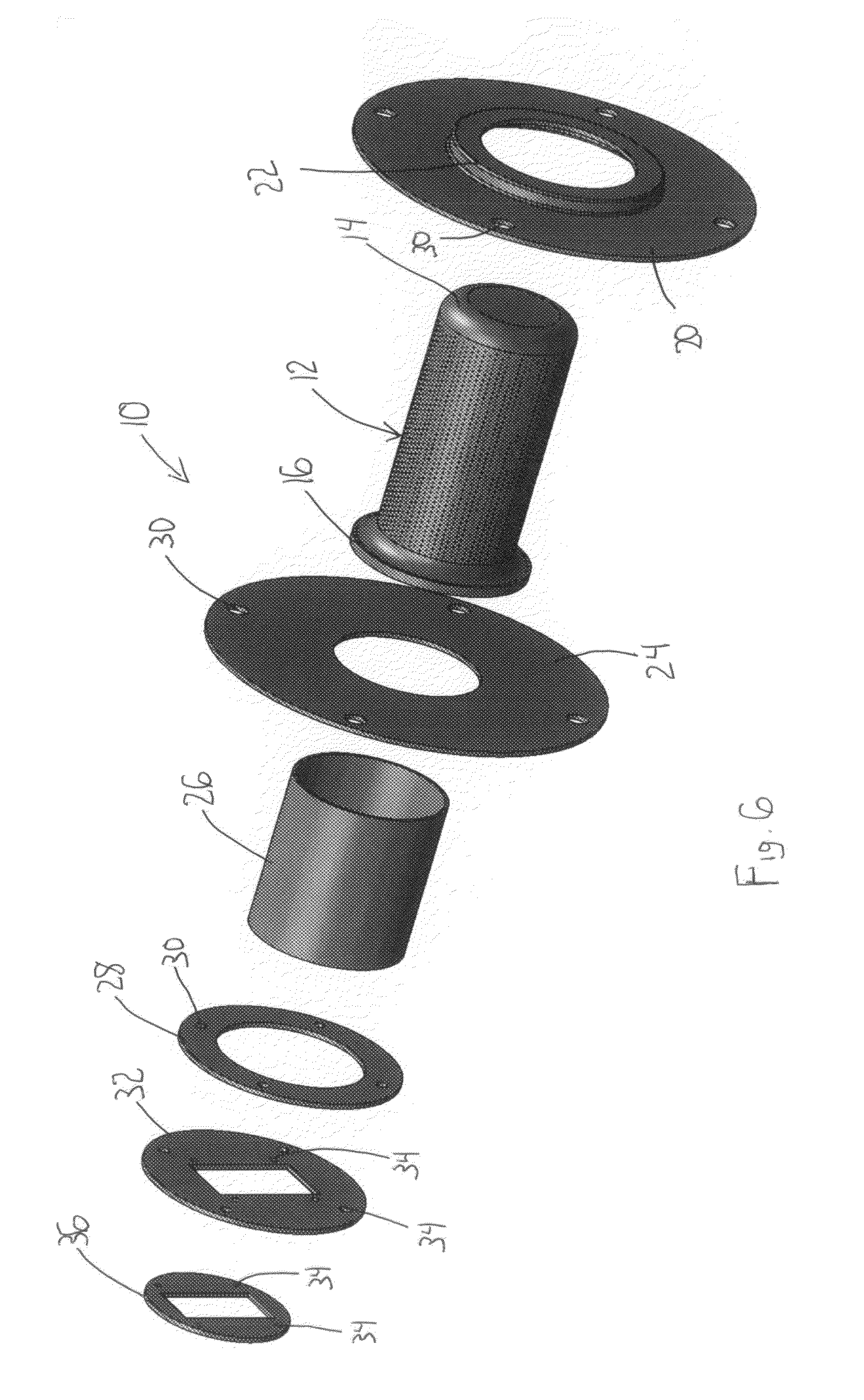
[0045]Referring to the drawings, there is shown a ceramic gas burner assembly 10 according to an embodiment of the present invention. The ceramic gas burner assembly 10 is a high efficiency low pollutant apparatus that may create and fill the demand for more efficient and cleaner burners. The ceramic gas burner assembly 10 has a solid ceramic cylindrical burner 12 that is used in gas fired appliances in any known commercial or residential applications. These applications may include but are not limited to kitchen ranges, instant hot water heaters, residential water heating, residential and commercial space heating, heating oils in deep fryers for commercial applications and the like. Generally, the cylindrical burner 12 is comprised of a cap, 14 a flange 16 and perforated cylinder 12 formed into a solid integrated unit. The present invention utilizes advanced ceramic technology and state of the art manufacturing technologies to produce unique cylindrical or other geometrical shaped...


PUM

PropertyMeasurementUnit
thicknessaaaaaaaaaa
diameteraaaaaaaaaa
outer diameteraaaaaaaaaa

Abstract

A gas burner for use in water heaters, boilers, cooking appliances or the like uses a ceramic cylindrical body to increase conductivity of the gas burner. The gas burner comprises a solid ceramic perforated tube and a flange arranged on one end of the tube. The burner assembly also compromises a cap arranged on the opposite end of the tube from that of the flange, wherein the tube has turn down characteristics of approximately 30 to 1. The tube is manufactured by molding a non-perforated shell within a die assembly. The non-perforated shell is then dried to a predetermined moisture content and machined with a plurality of orifices into the shell to create the burner tube for a ceramic burner assembly.

Description

BACKGROUND OF THE INVENTION[0001]1. Field of the Invention[0002]The present invention generally relates to a burner, and more particularly relates to a ceramic cylindrical burner for use in gas burner appliances and other applications.[0003]2. Description of Related Art[0004]Gas burners have been known for many years in the prior art. These gas burners are used in a variety of commercial and residential applications such as kitchen ranges, instant hot water heaters for residential water heating, boilers for residential and space heating, heating oils in deep fryers for commercial applications and the like. These typical gas burner applications have been the focus of global interests because of the recent energy crisis and the envioronmental concerns that have pushed industry toward alternative sources for green technologies. Many different types of material such as ceramics and high temperature alloys have been tested and used as combustion surfaces for gas burners in the prior art....

Claims


Application Information

Patent Timeline
Patent Type & Authority Applications(United States)
IPC IPC(8): F23D14/46C04B41/53
CPCF23D14/46F23D14/58F23D2213/00F23D2203/102F23D2212/10F23D2203/1012
Inventor MURRAY, CLINTICO, ROBERTAHMADY, FARSHID
Owner APOGEE ENGINEERED CERAMICS
Why Eureka
Try Eureka