
Electronic measuring device and method of converting serial data to parallel data for storage using the same
a technology of parallel data and measuring device, which is applied in the direction of measurement device, digital variable/waveform display, instruments, etc., can solve the problem of limited storage capacity of serial-parallel shifter, achieve accurate and effective data structure, increase memory use efficiency, and increase storage speed and processing efficiency
- Summary
- Abstract
- Description
- Claims
- Application Information
AI Technical Summary
Benefits of technology
Problems solved by technology
Method used
Image

Examples
Embodiment Construction
[0023]The detailed description and technical contents of the present invention will be explained with reference to the accompanying drawings. However, the drawings are illustrative only but not used to limit the present invention.
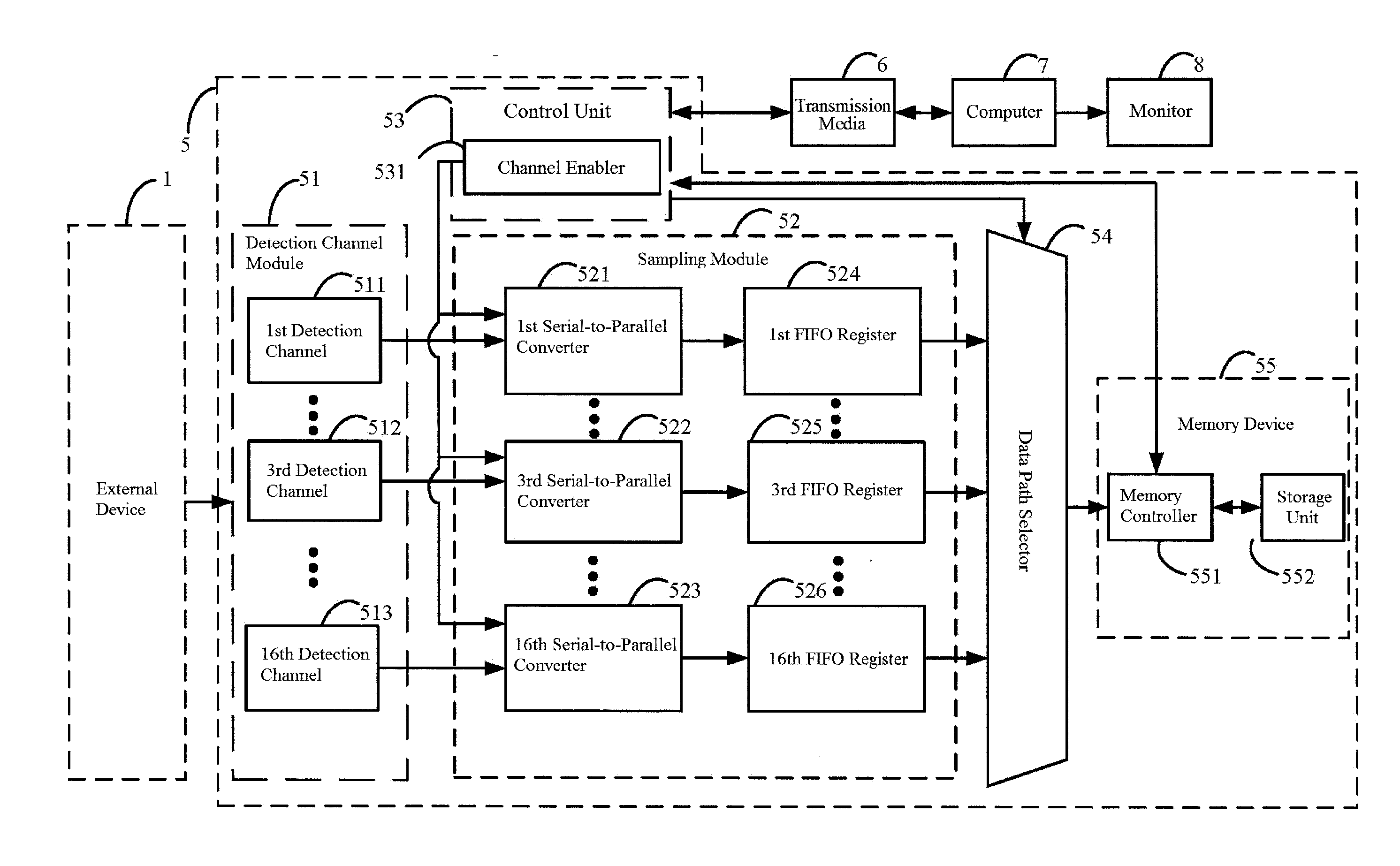
[0024]FIG. 3 is a block diagram of an embodiment according to the present invention. The block diagram shows the major components of the invention. As shown in FIG. 3, the electronic measuring device 5 is connected to an external device 1. The external device 1 sends electronic signal to the electronic measuring device 5 allowing a user to use the electronic measuring device 5 to conduct electronic measuring through the external device 1. The data collected by the electronic measuring device 5 can be transmitted to a computer 7 through a transmission interface 6. A monitor 8 is connected to the computer 7 to display the data to the user.
[0025]In this embodiment, the electronic measuring device 5 is a logic analyzer. Its main utility is to detect electronic ...
PUM
 Abstract
Description
Claims
Application Information