
Downhole tools having features for reducing balling, methods of forming such tools, and methods of repairing such tools

a technology of reducing balling and tools, which is applied in the field of downhole tools, can solve the problems of low penetration rate, too expensive to run higher mud flow rate, and rigs that may not have large pumps for drilling to the depths required

Active Publication Date: 2012-08-16
BAKER HUGHES INC
View PDF6 Cites 35 Cited by
  • Summary
  • Abstract
  • Description
  • Claims
  • Application Information

AI Technical Summary

Benefits of technology

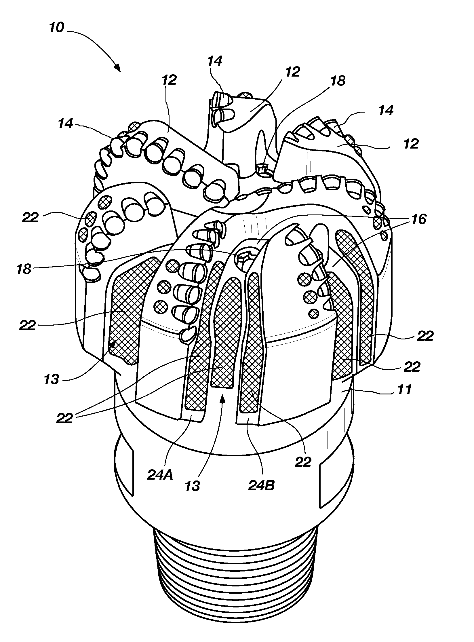
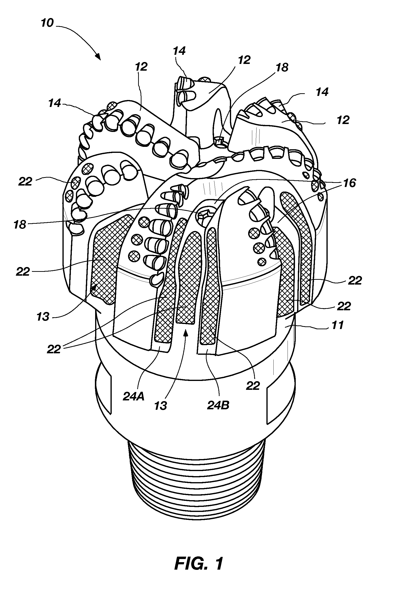
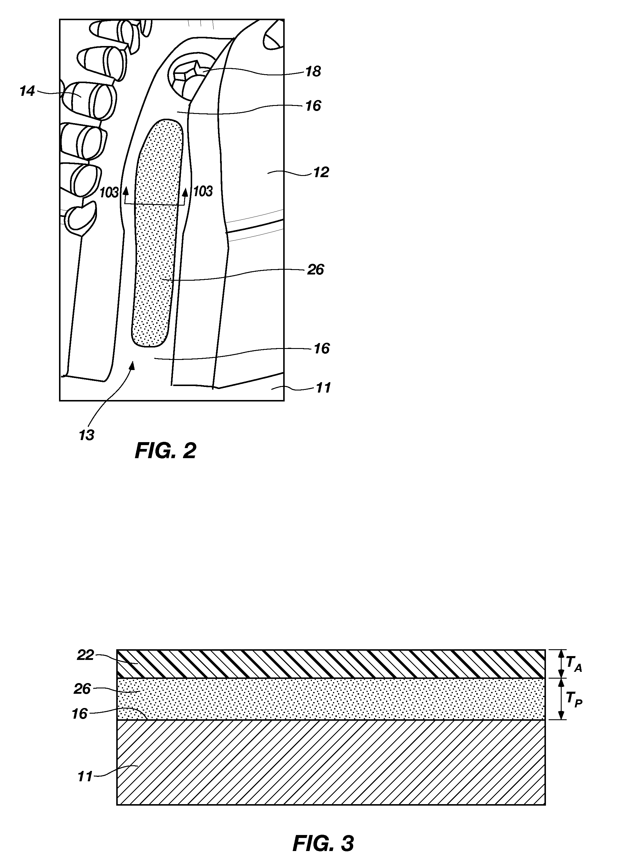
The present invention provides a downhole tool with a surface having a topographical pattern, which includes a recess or protrusion. The tool also includes an anti-balling material disposed over at least a portion of the surface, which is designed to reduce accumulation of formation cuttings when the tool is used to form or service a wellbore. The anti-balling material may be selected from a composition that prevents the formation cuttings from sticking to the surface of the tool. The tool may also include a porous mass over a surface of the body, with the anti-balling material disposed over at least a portion of the porous mass. The tool may be formed by methods that include forming the recess or protrusion, providing an anti-balling material over at least a portion of the surface, and attaching the anti-balling material to the body of the tool. The tool may also be repaired by replacing the insert with a new insert that has the anti-balling material. The technical effect of this invention is to improve the performance of downhole tools used in wellbore construction and servicing by reducing the accumulation of formation cuttings on the tool surface, which can lead to damage and reduced efficiency.

Problems solved by technology

Drilling tools used for casing and liner drilling usually have smaller fluid courses and are particularly prone to balling, causing a lower rate of penetration.
For example, some rigs may not have large pumps for drilling to the depths required.
Furthermore, operators sometimes find it too costly to run higher mud flow rates or find that high flow rates cause more wear and tear to the BHA.
Drilling with reduced or mitigated hydraulics has a tendency to cause balling.

Method used


Image

  • Downhole tools having features for reducing balling, methods of forming such tools, and methods of repairing such tools
  • Downhole tools having features for reducing balling, methods of forming such tools, and methods of repairing such tools
  • Downhole tools having features for reducing balling, methods of forming such tools, and methods of repairing such tools

Examples


embodiment 1

[0086] A downhole tool, comprising: a body having a surface comprising a topographical pattern defined by at least one of a recess extending into the surface and a protrusion protruding from the surface; and an anti-balling material disposed over at least a portion of the surface comprising the pattern therein, the anti-balling material having a composition selected to reduce accumulation of formation cuttings thereon when the downhole tool is used to form or service a wellbore.

[0087]Embodiment 2: The downhole tool of embodiment 1, wherein the anti-balling material comprises a hydrophobic polymer, a metal, a metal alloy, a ceramic, diamond, diamond-like carbon, graphite, molybdenum disulfide, boron nitride, or silicone.

[0088]Embodiment 3: The downhole tool of embodiment 2, wherein the anti-balling material comprises a mixture of a metal or metal alloy and a hydrophobic polymer material.

[0089]Embodiment 4: The downhole tool of embodiment 1, wherein the anti-balling material comprises...

embodiment 14

[0099] A downhole tool, comprising: a body having a surface comprising at least one recess extending into the surface of the body; and an insert disposed within the at least one recess, the insert comprising an anti-balling material having a composition selected to reduce accumulation of formation cuttings thereon when the downhole tool is used to form or service a wellbore.

[0100]Embodiment 15: The downhole tool of embodiment 14, wherein the surface of the body comprises a plurality of recesses extending into the surface of the body, and wherein the downhole tool further comprises an insert disposed in each recess of the plurality of recesses, each insert comprising the anti-balling material having the composition selected to reduce accumulation of formation cuttings thereon when the downhole tool is used to form or service a wellbore.

[0101]Embodiment 16: The downhole tool of embodiment 14, wherein the plurality of recesses comprises a plurality of discrete, laterally isolated reces...

embodiment 17

[0102] A downhole tool, comprising: a body having a surface; at least one porous mass over the surface of the body; and an anti-balling material disposed over the at least one porous mass, the anti-balling material having a composition selected to reduce accumulation of formation cuttings thereon when the downhole tool is used to form or service a wellbore.

[0103]Embodiment 18: The downhole tool of embodiment 17, wherein the at least one porous mass comprises a spray-deposited material.

[0104]Embodiment 19: The downhole tool of embodiment 18, wherein the body comprises tungsten carbide and the at least one porous mass comprises nickel aluminide.

[0105]Embodiment 20: The downhole tool of embodiment 17, wherein the anti-balling material comprises a fluoropolymer.

[0106]Embodiment 21: The downhole tool of embodiment 20, wherein the anti-balling material comprises a mixture of a metal or metal alloy and a fluoropolymer.

[0107]Embodiment 22: The downhole tool of embodiment 17, wherein the ant...


PUM

PropertyMeasurementUnit
thicknessaaaaaaaaaa
contact angleaaaaaaaaaa
temperaturesaaaaaaaaaa

Abstract

Downhole tools are provided with a topographical pattern, and anti-balling material is provided over the topographical pattern. The topographical pattern may be defined by at least one of a plurality of recesses extending into a surface of a body of the tool and a plurality of protrusions protruding from the surface. Downhole tools include an insert disposed within a recess in a body, and the insert comprises an anti-balling material having a composition selected to reduce accumulation of formation cuttings on the tools when the tools are used to form or service a wellbore. Downhole tools include anti-balling material disposed over a porous mass provided over the surfaces of the tools. Methods of forming downhole tools include providing anti-balling material over features on and / or in a surface of a body of a tool. Methods of repairing downhole tools include removing an insert therefrom and disposing a replacement insert therein.

Description

CROSS-REFERENCE TO RELATED APPLICATIONS[0001]This application is a continuation of U.S. patent application Ser. No. 13 / 006,323, filed Jan. 13, 2011, pending, which claims the benefit of U.S. Provisional Patent Application Ser. No. 61 / 295,989, filed Jan. 18, 2010, entitled “Drill Bits and Other Downhole Tools Having Features for Reducing Balling, and Related Methods,” the disclosure each of which is incorporated herein by reference in its entirety.TECHNICAL FIELD[0002]Embodiments of the present invention relate to downhole tools, such as earth-boring rotary drill bits, and, more particularly, to downhole tools having features for reducing the adhesion of formation cuttings thereto during the formation of a wellbore, and to methods of forming such downhole tools.BACKGROUND[0003]Wellbores are formed in subterranean formations for various purposes including, for example, extraction of oil and gas from the subterranean formation and extraction of geothermal heat from the subterranean for...

Claims


Application Information

Patent Timeline
Patent Type & Authority Applications(United States)
IPC IPC(8): E21B10/36B23P15/32B21K5/04
CPCE21B10/46Y10T29/49982E21B17/1085Y10T29/49734E21B10/62B23P15/32B23P15/28E21B10/54B23P6/00
Inventor PATEL, SURESH G.VEMPATI, CHAITANYA K.RADFORD, STEVEN R.MARVEL, TIMOTHY K.STAUFFER, BRUCEBUTLER, GEORGE I.
Owner BAKER HUGHES INC
Learn More