Control rod for high temperature gas reactor

a gas reactor and control rod technology, applied in the direction of nuclear reactors, nuclear elements, greenhouse gas reduction, etc., can solve the problems of inability to make large hanging loads, inability to use control rods repeatedly, etc., to achieve the effect of reducing the weight of the support member, improving safety, and reducing the weight received by the joining means

Active Publication Date: 2012-08-16
TOYO TANSO KK
View PDF1 Cites 2 Cited by
  • Summary
  • Abstract
  • Description
  • Claims
  • Application Information

AI Technical Summary

Benefits of technology

[0013]When the member / members other than the neutron absorber is / are made of a C / C composite material or a SiC / SiC composite material, which has high shear strength and good heat resistance, the heat resistance can be increased and the mechanical strength can be improved. In particular, the SiC / SiC composite material has high strength, higher shear strength, and moreover excellent neutron damage resistance. For this reason, when this material is used, the above-described advantageous effects can be exhibited more significantly. Nevertheless, it is preferable that the SiC / SiC composite material be used only for the components that require strength and the like, as will be described later, because the SiC / SiC composite material is more costly than the C / C composite material. Moreover, when the member / members other than the neutron absorber is / are made of the above-mentioned material, it is possible to use the control rod repeatedly in an inert atmosphere at 2000° C., and there is no constraint on the operating conditions of the nuclear reactor because of the use temperature limit of the control rod.
[0014]It is desirable that the support member have a side wall and a hollow portion surrounded by the side wall and extending in a vertical direction.
[0015]When the support member has the hollow portion extending in a vertical direction, the weight of the support member can be reduced, so the weight received by the joining means can be accordingly reduced. This inhibits the high-temperature gas reactor control rod from damage. Therefore, the safety can be improved further. Moreover, the amount of the required raw material is less, so the cost of the high-temperature gas reactor control rod can be reduced. In addition, since the side wall exists around the hollow portion, the strength of the support member can be inhibited from degrading.
[0016]It is desirable that the joining means have a shaft horizontally inserted through two holes formed in the side wall of the support member, and a ring-shaped joining belt through which the shaft passes.
[0017]Thus, the control rod elements can be joined to each other merely by providing the shaft horizontally inserted through the two holes formed in the side wall of the support member and the ring-shaped joining belt through which the shaft passes. Therefore, it becomes possible to join the control rod elements to each other easily at low cost.
[0018]It is desirable that the joining belt have a plate shape.

Problems solved by technology

However, in the case of a large-scale high temperature gas reactor, in which the reactor core output power and the output power density are large and the temperature conditions are harsh, the control rod element made of a metallic material may cause the metal to melt, making it impossible to use the control rod repeatedly.
This has been a technical problem.
For this reason, hanging load cannot be made large (in other words, the number of control rod elements joined is limited).
Moreover, the thread may break with, for example, small shaking.

Method used


Image

  • Control rod for high temperature gas reactor
  • Control rod for high temperature gas reactor
  • Control rod for high temperature gas reactor

Examples


first embodiment

[0060]A first embodiment of the present invention will be described hereinbelow with reference to FIGS. 1 through 15.

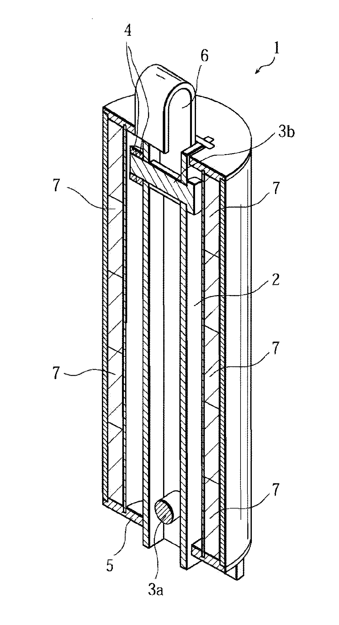
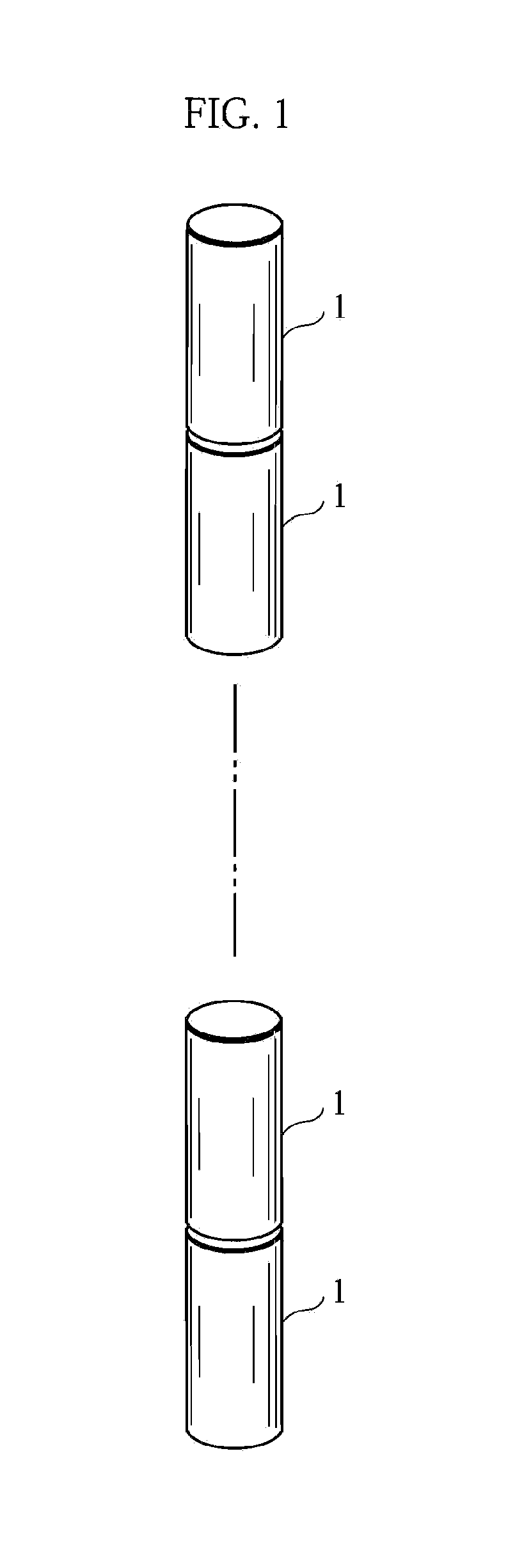
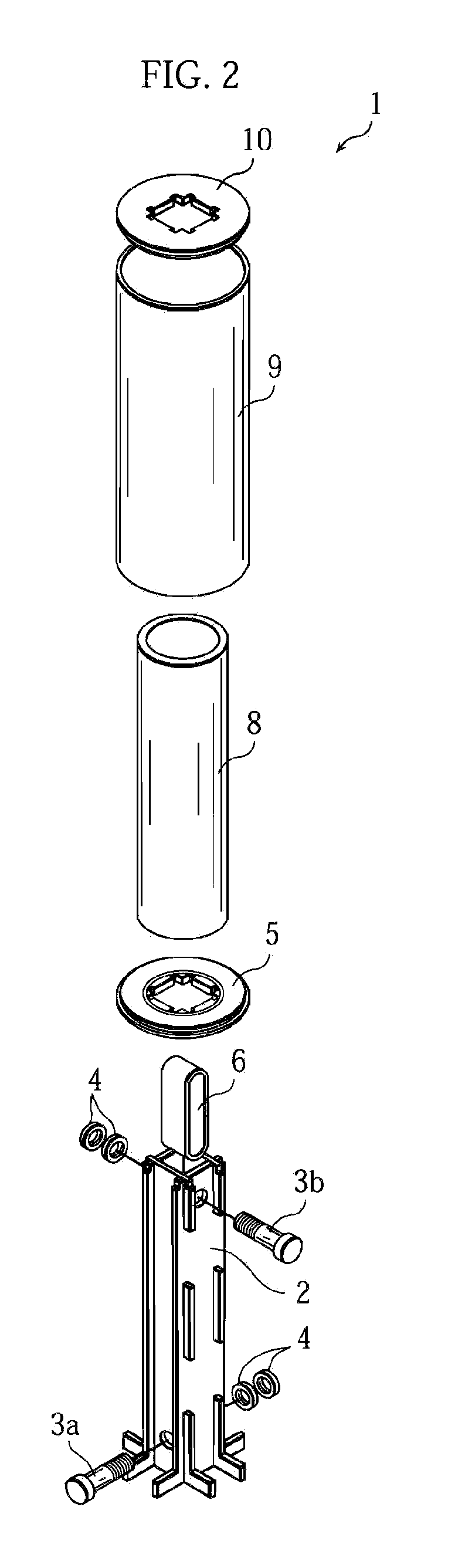
[0061]As illustrated in FIG. 1, a high-temperature gas reactor control rod of the present invention has a structure in which a plurality of control rod elements 1 are joined to each other in a vertical direction (up / down direction). A slight gap is provided between the control rod elements 1. The gap is provided between the control rod elements 1 because, in that way, joining bolts 3a and 3b can move upward and downward within a later-described joining belt 6 when stress is applied to the control rod element 1 in an up / down direction, so that the control rod element 1 can be prevented from damage. As illustrated in FIGS. 2 to 4 (note that the neutron absorber 7 is not shown in FIG. 2), the control rod element 1 has an outer cylinder 9, an inner cylinder 8, neutron absorbers 7 disposed between the cylinders 8 and 9, a columnar support member 2 disposed in the inner cyl...

second embodiment

[0081]A second embodiment of the present invention will be described hereinbelow with reference to FIGS. 16 through 18.

[0082]As illustrated in FIG. 16, a control rod element 1 according to the second embodiment has an outer cylinder 9, an inner cylinder 8, neutron absorbers 7 disposed between the cylinders 8 and 9, a cylindrical columnar support member 2 disposed in the inner cylinder 8, a lower lid 5, disposed at the lower ends of the cylinders 8 and 9, for supporting the neutron absorbers 7 at the bottom, and a support ring 50, and securing screws 51.

[0083]The outer cylinder 9 has a bell-like shape tapered toward the top, and it has a structure in which the neutron absorbers 7 and the inner cylinder 8 are inserted from a lower opening 52. In the upper end of the outer cylinder 9, a through hole 53 is provided for passing the columnar support member 2 therethrough. In addition, at the center of the disk-shaped lower lid 5 disposed at the lower end of the inner cylinder 8, a through...

third embodiment

[0092]A third embodiment will be described with reference to FIG. 19. The structures of the inner cylinder, the neutron absorbers, and the support member are the same as those in the second embodiment, and therefore, these components are not shown in FIG. 19.

[0093]As illustrated in FIG. 19, through holes 70 are formed intermittently along the circumferential direction slightly above the lower end of the outer cylinder. Flat plate-shaped support plates 71 are inserted in the through holes 70. Both ends of each of the support plates 71 are supported from below by the outer cylinder 9 that is below the through holes 70, whereby the neutron absorbers and the inner cylinder are supported from below by the support plates 71. A through hole 55 for inserting the support member 2 therethrough is provided near the lengthwise center of each of the support plates 71.

[0094]The number of the support plates 71 disposed using the through holes 70 is not limited to two, as described above, but may b...


PUM


Abstract

A high-temperature gas reactor control rod is provided that does not degrade the joining state between the control rod elements even when stress is applied thereto, and that can improve the safety of the high temperature gas reactor remarkably by improving the heat resistance thereof.The high-temperature gas reactor control rod has a plurality of control rod elements (1) each having a neutron absorber (7) between an outer cylinder (9) and an inner cylinder (8) that form a double cylindrical tubular shape, the control rod elements (1) joined to each other in a vertical direction, characterized by: a columnar support member (2) for supporting at least the neutron absorber (7), disposed in the inner cylinder (8); and joining means for joining to another control rod element (1), provided at least one of upper and lower ends of the support member (2).

Description

TECHNICAL FIELD[0001]The present invention relates to a high-temperature gas reactor control rod, which is used for high temperature gas reactors in nuclear electric power generation.BACKGROUND ART[0002]The high-temperature gas reactor control rod, which is used for high temperature gas reactors in nuclear electric power generation, has a structure in which a plurality of control rod elements are joined to each other in a vertical direction (up / down direction). Each of the control rod elements accommodates a neutron absorber such as B4C.[0003]Conventionally, a metal-based high-temperature gas reactor control rod has been used for the control rod element serving as a means to accommodate a neutron absorber in a high temperature gas reactor. However, in the case of a large-scale high temperature gas reactor, in which the reactor core output power and the output power density are large and the temperature conditions are harsh, the control rod element made of a metallic material may cau...

Claims


Application Information

Patent Timeline
Patent Type & Authority Applications(United States)
IPC IPC(8): G21C7/10
CPCG21C7/10G21C7/24G21C7/107Y02E30/39G21C1/07Y02E30/33Y02E30/30
Inventor HIRAOKA, TOSHIHARUKONISHI, TAKASHIYAMAJI, MASATOSHIMACHINO, HIROSHISHIBATA, TAIJUSAWA, KAZUHIRO
Owner TOYO TANSO KK
Why Eureka
Try Eureka