Method for manufacturing a HTS coated tape with laser beam cutting

a technology of superconductor and laser beam cutting, which is applied in the direction of manufacturing tools, superconductor devices, laser beam welding apparatus, etc., can solve the problems of severe reduction of the overall critical current, partial or complete damage to the hts structure, and deterioration degree, so as to improve the critical current, the effect of improving the critical current and modifying the hts layer

Inactive Publication Date: 2012-08-23
OSWALD ELEKTROMOTOREN +1
View PDF2 Cites 11 Cited by
  • Summary
  • Abstract
  • Description
  • Claims
  • Application Information

AI Technical Summary

Benefits of technology

[0025]In a preferred further development, the at least one annealing step is performed between or after the at least two steps of the deposition of the metallic protection layer. Thus properties of the HTS layer may be altered or adapted, in particular improving the critical current by introducing precious metal of the protection layer and/or oxygen at the grain boundaries of the HTS material.
[0026]In another advantageous variant, the laser beam cutting is done with an incidence of the laser beam from the side of the partially prepared coated tape which is opposite to the side where the at least one buffer layer and the HTS film are deposited. This laser beam cutting “from the back” is more gentle to the buffer layer and the HTS layer, and results in improved critical current, as compared to a cutting “from the top”.
[0027]In an advantageous variant, the deposition of the metallic protection layer comprises a vacuum deposition process of a precious metal or precious metal alloy. This grants a high quality deposition, in particular low in impurities.
[0028]Another advantageous variant provid...

Problems solved by technology

However, when applying these techniques to HTS coated conductors, partial or complete damage of the HTS structure results.
Such deterioration results in a severe reduction of the overall critical current (with a deterioration degree depending on materials employed) and a decrease in the critical temperature of the HTS ...

Method used


Image

  • Method for manufacturing a HTS coated tape with laser beam cutting
  • Method for manufacturing a HTS coated tape with laser beam cutting
  • Method for manufacturing a HTS coated tape with laser beam cutting

Examples


Embodiment Construction

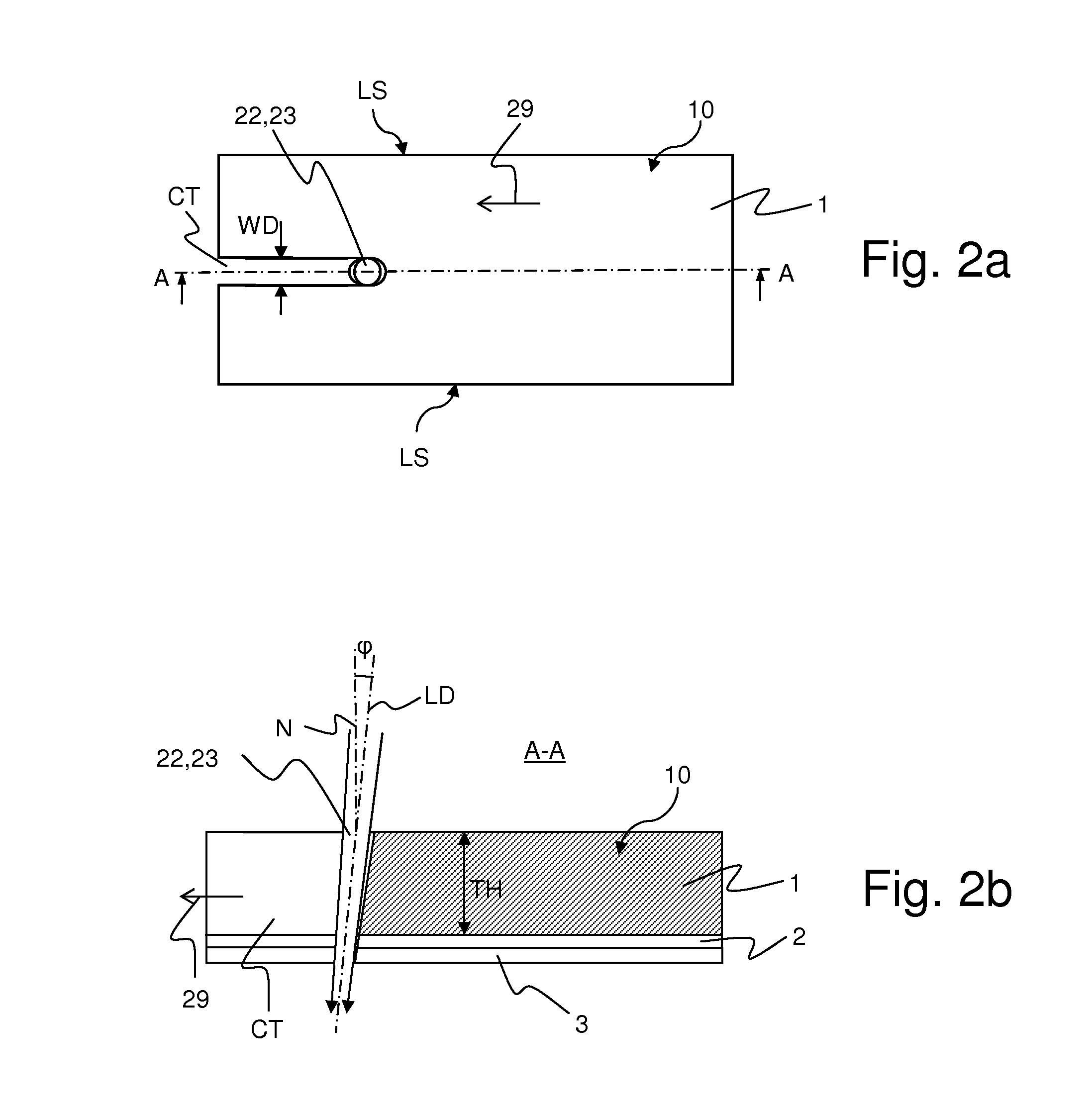
[0040]The invention presents a novel method for manufacturing an HTS coated tape. It comprises processing of a substrate tape, deposition of at least one buffer layer, deposition of an HTS film, deposition of a metallic protection layer, deposition of a metallic shunt layer, and cutting of the tape in order to provide a desired tape form. The cutting of the tape is performed via laser beam cutting. Later technique is typically applied together with a liquid flow directed along the laser beam and guiding this beam towards the tape. In accordance with the invention, the laser beam cutting is applied in between processing steps prior to the deposition of the metallic shunt layer.

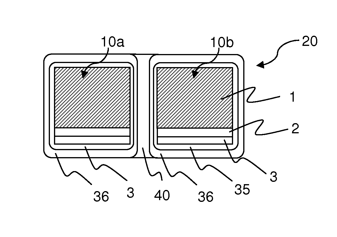
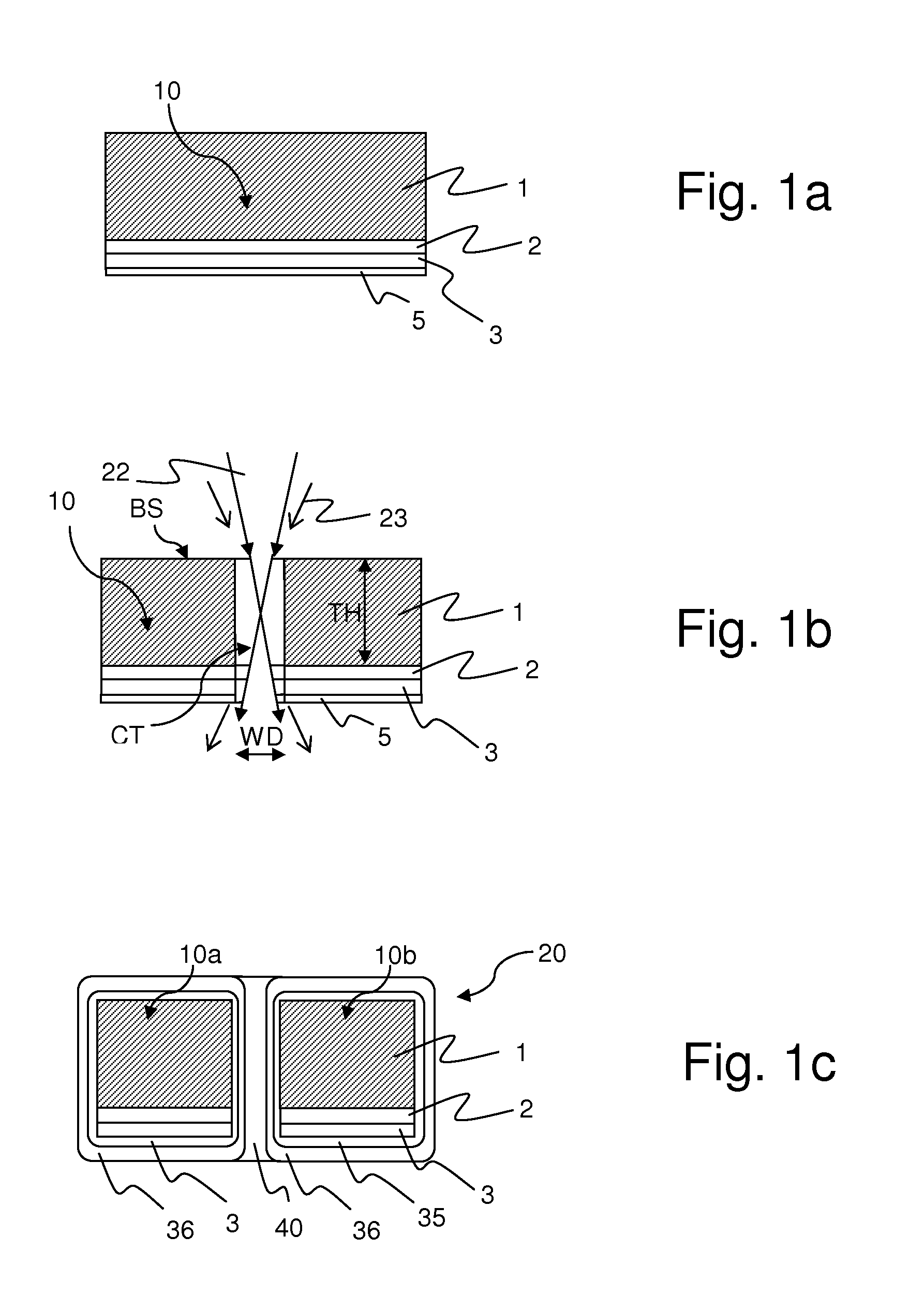
[0041]FIGS. 1a through 1c illustrate the steps of the inventive method by way of example.

[0042]On a substrate tape 1, a buffer layer 2 (or alternatively several buffer layers) is deposited. On top of the buffer layer 2, a HTS film 3 is deposited. Further, a first part 5 of a metallic protection layer is deposit...


PUM

PropertyMeasurementUnit
Lengthaaaaaaaaaa
Lengthaaaaaaaaaa
Lengthaaaaaaaaaa

Abstract

A method for manufacturing a high temperature superconductor (=HTS) coated tape (20), with the following steps: preparation of a substrate tape (1), deposition of at least one buffer layer (2), deposition of an HTS film (3), deposition of a metallic protection layer (35) on the HTS film (3) and deposition of a metallic shunt layer (36) is characterized in that, prior to deposition of the metallic shunt layer (36), the partially prepared coated tape (10) undergoes a laser beam cutting in order to provide a desired tape form, wherein the laser beam cutting is applied together with a gas flow and/or a liquid flow (23). The method reduces the loss of critical current and reduces or avoids a deterioration of the critical temperature in a HTS coated tape due to tape cutting.

Description

[0001]This application claims Paris Convention priority of EP 11 154 950.7 filed Feb. 18, 2011 the complete disclosure of which is hereby incorporated by reference.BACKGROUND OF THE INVENTION[0002]The invention relates to a method for manufacturing of a high temperature superconductor (=HTS) coated tape, with the following steps:a) preparation of a substrate tape,b) deposition of at least one buffer layer,c) deposition of an HTS film,d) deposition of a metallic protection layer on the HTS film,e) deposition of a metallic shunt layer.[0003]A layered HTS structure, comprising a substrate, a buffer layer, an HTS layer, a capping layer and a stabilizer layer, or a corresponding method for its manufacturing, respectively, are known from U.S. Pat. No. 7,774,035 B2.[0004]The invention deals with methods for manufacturing of high temperature superconducting (HTS) coated tapes and may be employed, in particular, in the fields of building of motors, magnets, generators, energy transmission an...

Claims


Application Information

Patent Timeline
IPC IPC(8): B23K26/00
CPCH01L39/2464Y10T29/49014H01L39/24H01L39/248H10N60/0661H10N60/0801H10N60/01
Inventor OSWALD, JOHANNESOSWALD, BERNHARDREIS, THOMASRUTT, ALEXANDERUSOSKIN, ALEXANDER
Owner OSWALD ELEKTROMOTOREN
Why Eureka
Try Eureka