Method for controlling power factor of three-phase converter, method for controlling reactive power of three-phase converter, and controller of three-phase converter

a technology of three-phase converters and controllers, applied in the direction of electric variable regulation, process and machine control, instruments, etc., can solve the problems of periodic maintenance, voltage sag in the state where the three phases are balanced or unbalanced, and the effect of unfavorable responsivity to the power factor variation

Active Publication Date: 2012-08-23
KYOSAN ELECTRIC MFG CO LTD
View PDF2 Cites 46 Cited by
  • Summary
  • Abstract
  • Description
  • Claims
  • Application Information

AI Technical Summary

Benefits of technology

[0054]In order to control the three-phase PWM converter, it is necessary to have a relationship of 120° out of phase between the wye-phase voltages. Therefore, specific wye-phase voltages which are 120° out of phase with each other have to be selected from the infinite number of combinations of wye-phase voltages. When these specific wye-phase voltages which are 120° out of phase with each other are selected, a positive-phase-sequence voltage becomes in phase with a particular phase (a-phase) of the wye-phase voltages, and a DC component as a control target can be extracted according to the subsequent dq-axis conversion process. Therefore, it is convenient for the control of the three-phase PWM converter. In addition, a phase angle of the negative-phase-sequence voltage and a phase angle of the zero-phase-sequence voltage with respect to the positive-phase-sequence voltage, indicate the same angle in the direction opposite to each other, therefore enabling the zero-phase-sequence voltage to be derived.
[0124]According to the present invention, the three-phase PWM converter is controlled based on the instantaneous wye-phase voltages obtained from the actually measured instantaneous line voltages, and it is possible to control the power factor and the reactive power with a favorable responsivity to the power factor variation in the three-phase line voltages, simultaneously with compensating for unbalanced voltages.

Problems solved by technology

It is known that occurrence of voltage reduction on the power source side, such as instantaneous voltage drop (voltage sag) and a long-term voltage reduction, has an impact on the load side which receives power supply from the power source, such as production line stop and defects in manufactured goods.
Application of such various loads or influences such as weather phenomenon and accident phenomenon may occasionally cause a voltage sag in the state where the three phases are balanced or unbalanced.
There are following problems in the voltage sag compensator as described above, i.e., not only this system requires equipment investment for installing a large-sized electric storage device or a capacitor unit, but also periodic maintenance is necessary.
However, in general, in order to control the three-phase PWM converter in which PFC (Power Factor Correction) is incorporated, it is necessary to derive wye-connection three-phase unbalanced phase voltages which are 120° out of phase with each other.
In the case where a value of the phase advance capacitor is fixed, the power factor becomes a leading power factor due to occurrence of excessive compensation for the reactive power in the case where the power consumption drops.

Method used


Image

  • Method for controlling power factor of three-phase converter, method for controlling reactive power of three-phase converter, and controller of three-phase converter
  • Method for controlling power factor of three-phase converter, method for controlling reactive power of three-phase converter, and controller of three-phase converter
  • Method for controlling power factor of three-phase converter, method for controlling reactive power of three-phase converter, and controller of three-phase converter

Examples


Embodiment Construction

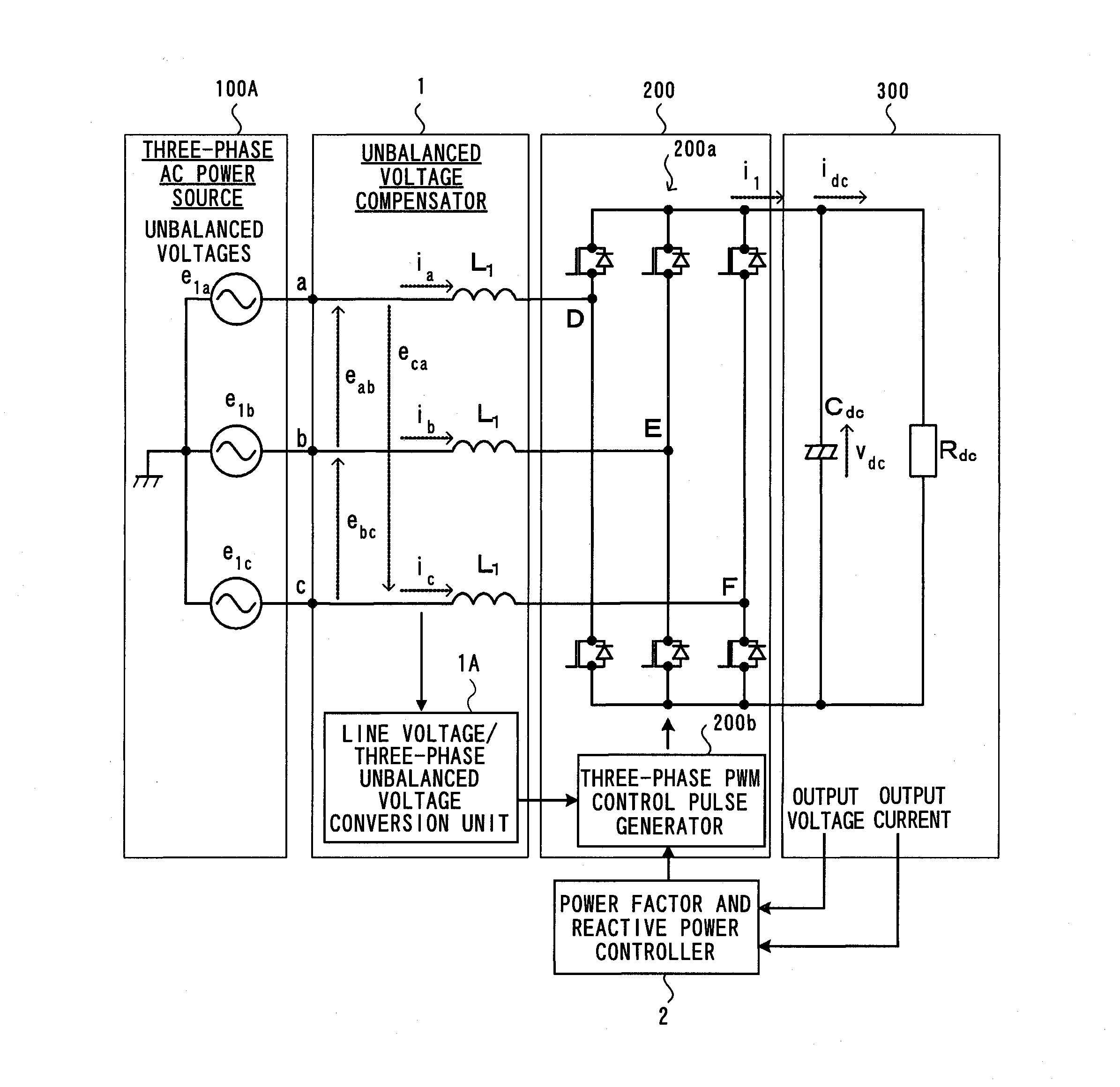
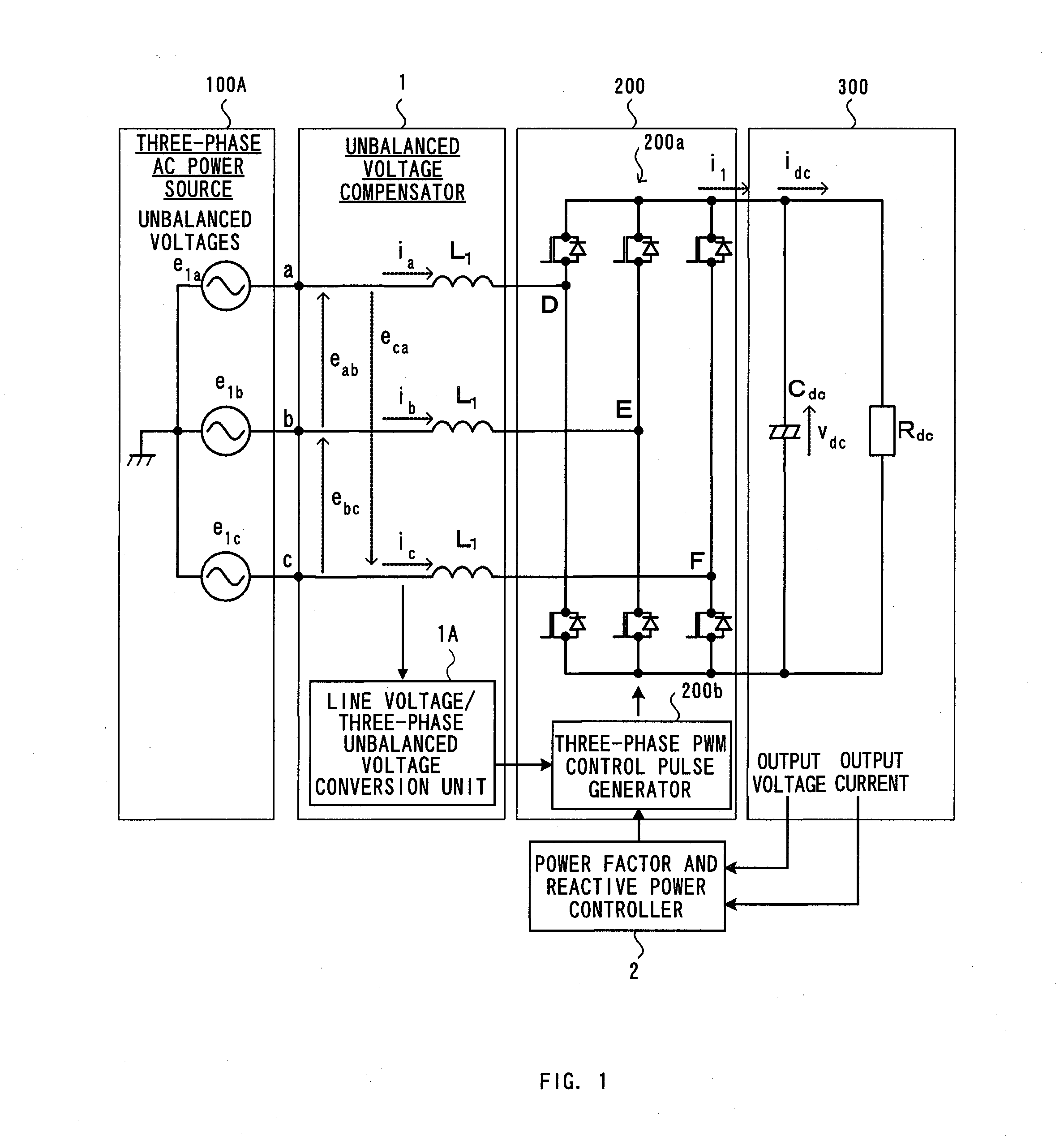
[0143]Hereinafter, preferred embodiments of the present invention will be explained in detail with reference to the accompanying drawings. With reference to FIG. 2 to FIG. 9, the power factor and reactive power control of the present invention will be explained, taking a three-phase converter as an example, and experimental results of the embodiments will be explained with reference to FIG. 10 to FIG. 15.

[0144]With reference to FIG. 2, a schematic configuration of the power factor and reactive power control of the present invention will be explained. In FIG. 2, a three-phase AC power source 100 supplies three-phase AC power, and the three-phase converter 200 subjects the three-phase AC power to the PWM conversion, and DC voltage is outputted to the DC load 300.

[0145]The three-phase converter according to the present invention is provided with the unbalanced voltage compensator 1, and the power factor and reactive power controller 2. The unbalanced voltage compensator 1 compensates f...


PUM


Abstract

In power conversion according to the three-phase converter, symmetrical component voltage values of a balanced system are calculated from wye-phase voltages on the three-phase AC input side of the three-phase converter. On the DC output side thereof, the power factor is set, an average active power value is calculated from an output voltage value and an output current value, and an average reactive power is calculated from the set power factor. On the basis of the symmetrical component voltage values, the average active power, and the active reactive power, a compensation signal for compensating for unbalanced voltages of the three-phase AC voltages and a control signal for controlling the power factor are generated, and according to the compensation signal and the control signal, a control signal for outputting DC is generated.

Description

BACKGROUND OF THE INVENTION[0001]1. Field of the Invention[0002]The present invention relates to unbalanced voltage compensation according to a three-phase converter, and more particularly, it relates to power factor control and reactive power control for improving a power factor and reactive power in a three-phase converter which converts three-phase AC power into DC power.[0003]2. Description of the Related Art[0004]It is known that occurrence of voltage reduction on the power source side, such as instantaneous voltage drop (voltage sag) and a long-term voltage reduction, has an impact on the load side which receives power supply from the power source, such as production line stop and defects in manufactured goods. In particular, since it has a significant impact on semiconductor manufacturing equipment, standards are established regarding the voltage sag; “SEMI F47-0200” (non-patent document 1), and “SEMI F47-0706” (non-patent document 2) (non-patent document 2). As for a testing...

Claims


Application Information

Patent Timeline
Patent Type & Authority Applications(United States)
IPC IPC(8): G05F1/70
CPCY02B70/126H02M3/1584H02M1/4208Y02B70/10Y02P80/10H02M1/42H02M7/155
Inventor YUZURIHARA, ITSUOTAKAYANAGI, ATSUSHIHATA, YOSHIHISAOKANO, TSUYOSHI
Owner KYOSAN ELECTRIC MFG CO LTD
Why Eureka
Try Eureka