System and method for enhanced contrast mr imaging

a contrast imaging and enhanced contrast technology, applied in the field ofMR imaging, can solve the problems of increased blurring, insufficient flow difference of arteries,

Active Publication Date: 2012-08-23
GENERAL ELECTRIC CO
View PDF16 Cites 11 Cited by
  • Summary
  • Abstract
  • Description
  • Claims
  • Application Information

AI Technical Summary

Benefits of technology

[0010]In accordance with yet another aspect of the invention, a non-transitory computer readable medium having thereon a computer program comprising instructions, which, when executed by a computer, cause the computer to prescribe a first fast spin echo (FSE) scan sequence including a first series of RF pulses having a first flip angle sequence and to scan an imaging object based on the first FSE scan sequence to acquire a first MR data set. The instructions also cause the computer to prescribe a second FSE scan sequence including a second series of RF pulses having a second flip angle sequence and to scan the imaging object based on the second FSE scan sequence to acquire a second MR data set. The second flip angle sequence is different from the first flip angle sequence. In addition, the instructions cause the computer to reconstruct a first image and a second image based on the first and second MR data sets, respectively and to create a difference image based on the first and second images.

Problems solved by technology

However, although the subtracted images depict the systolic faster flowing arteries, arteries that do not exhibit enough of a flow difference between the systole and diastole phases are likely to be subtracted out in a final flow difference image.
Although such a schema of modifying the readout spoilers between the two acquisitions benefits in the visualization of slower flowing arteries, it may also result in 1) an increased blurring due to longer echo spacing (i.e., since the spoiler gradient amplitudes need to modified in real-time in between the acquisitions of each of the images), 2) an enhanced background signal on the subtracted image since the eddy currents during the two acquisitions will be different, and 3) the presence of fine line artifacts due to uncrushed free induction decay signal between the refocus pulses since the readout crushers are different between the two acquisitions.

Method used


Image

  • System and method for enhanced contrast mr imaging
  • System and method for enhanced contrast mr imaging
  • System and method for enhanced contrast mr imaging

Examples


Embodiment Construction

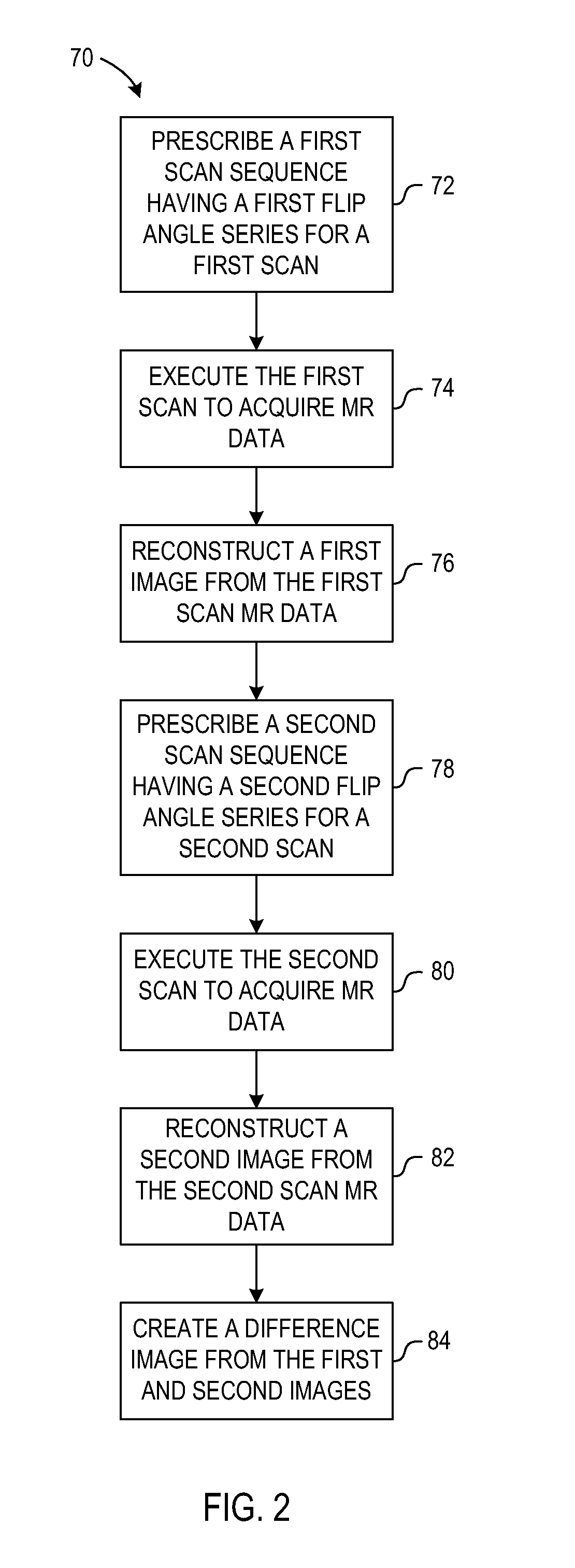
[0019]A system and method are provided that perform multiple MR image scans to acquire data where the flip angles for at least some of the refocusing pulses of the RF pulse sequence for a first MR image scan are distinct from the corresponding refocusing pulses of the RF pulse sequence for a second MR image scan. First and second MR images are reconstructed based on the first and second MR image scans, and a single image is created based on the first and second MR images that have a high contrast while having reduced artifacts.

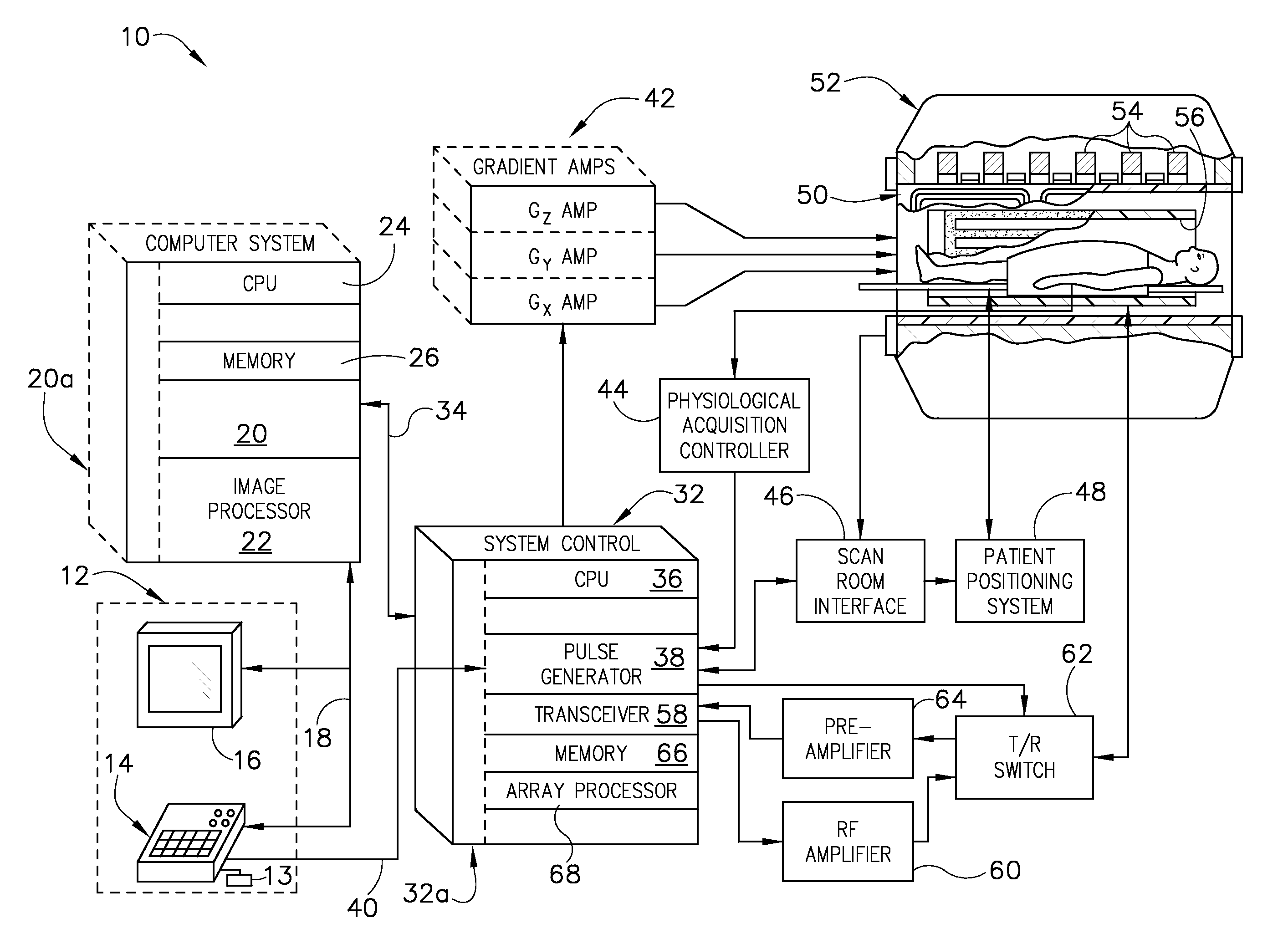
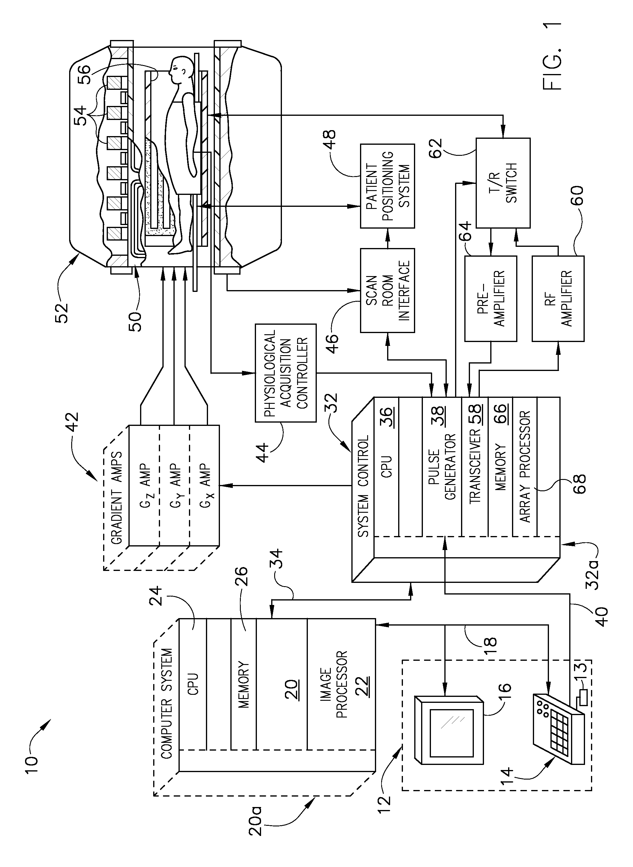
[0020]Referring to FIG. 1, the major components of a magnetic resonance imaging (MRI) system 10 incorporating an embodiment of the invention are shown. The operation of the system is controlled for certain functions from an operator console 12 which in this example includes a keyboard or other input device 13, a control panel 14, and a display screen 16. The console 12 communicates through a link 18 with a separate computer system 20 that enables an operator t...


PUM


Abstract

A system and method for enhanced contrast MR imaging include a computer programmed to perform a first scan of an imaging object based on a first fast spin echo (FSE) scan sequence comprising a first series of RF pulses having a first flip angle sequence to acquire a first MR data set and perform a second scan of the imaging object based on a second FSE scan sequence comprising a second series of RF pulses having a second flip angle sequence, wherein the second flip angle sequence is different from the first flip angle sequence to acquire a second MR data set. The computer is further programmed to generate a difference image based on the first and second MR data sets.

Description

BACKGROUND OF THE INVENTION[0001]Embodiments of the invention relate generally to MR imaging and, more particularly, to a system and method for enhanced contrast MR imaging.[0002]When a substance such as human tissue is subjected to a uniform magnetic field (polarizing field B0), the individual magnetic moments of the spins in the tissue attempt to align with this polarizing field, but precess about it in random order at their characteristic Larmor frequency. If the substance, or tissue, is subjected to a magnetic field (excitation field B1) which is in the x-y plane and which is near the Larmor frequency, the net aligned moment, or “longitudinal magnetization”, MZ, may be rotated, or “tipped”, into the x-y plane to produce a net transverse magnetic moment Mt. A signal is emitted by the excited spins after the excitation signal B1 is terminated and this signal may be received and processed to form an image.[0003]When utilizing these signals to produce images, magnetic field gradient...

Claims


Application Information

Patent Timeline
Patent Type & Authority Applications(United States)
IPC IPC(8): G01R33/48
CPCG01R33/5635G01R33/5617
Inventor SUBRAMANIAN, RAMAN KRISHNANBUSSE, REED F.
Owner GENERAL ELECTRIC CO
Why Eureka
Try Eureka