

Pseudo Digital Gain Control for Broadband Tuner
a broadband tuner and gain control technology, applied in the direction of amplification control details, pulse automatic control, electrical apparatus, etc., can solve the problems of improper operation of subsequent circuitry and devices receiving signals, signal distortion, and subsequent demodulator circuits that may not operate properly when subjected, so as to simplify the overall circuit design and reduce circuitry. , the effect of increasing bandwidth
- Summary
- Abstract
- Description
- Claims
- Application Information
AI Technical Summary
Benefits of technology
Problems solved by technology
Method used
Image

Examples
Embodiment Construction
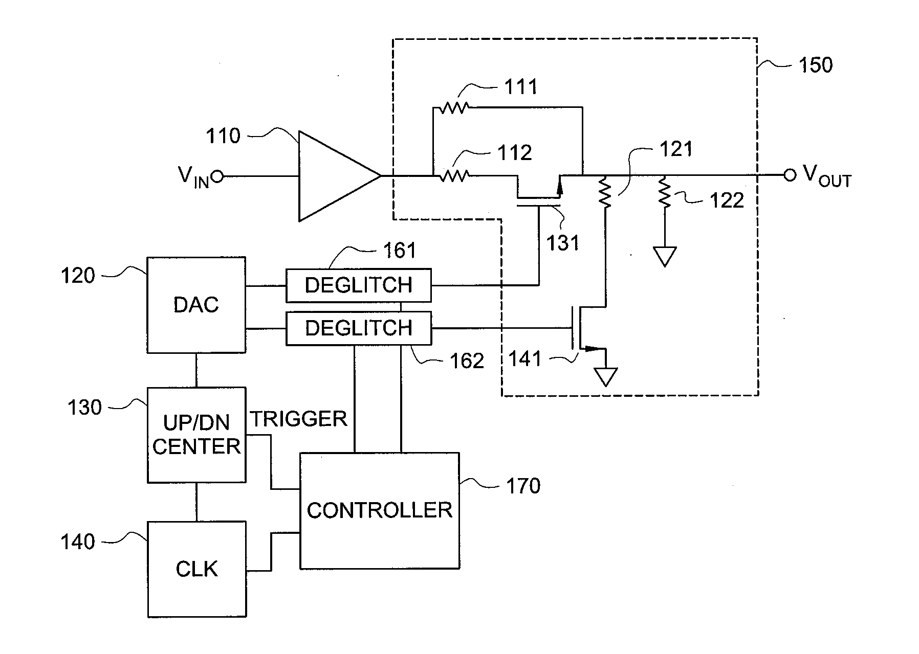
[0020]FIG. 1 is a circuit diagram of an automatic gain control circuit (AGC) implemented as switched output Attenuator 150 having switching elements in the form of FETs 131 and 141 controlled by an incremental step moderating circuit according to an embodiment of the present invention. The moderating circuit includes DAC 120, Up / Down Counter 130, Clock 140, Deglitch Circuits 161, 162 and Controller 170 that act in concert to cause the switching elements to gradually turn on or off over some transition period of gradual or stepwise increasing or decreasing conductance levels. Thus, within the larger intervals between levels selectable or settable by turning FETs 131 and 141 completely on and off, the moderating circuitry implements a sequence of smaller, “sub-interval” stepped or incremental transitions that more gradually change the signal level output while transition between selectable / programmable levels during some transition period.
[0021]Controller 170 includes logic in the for...
PUM
 Abstract
Description
Claims
Application Information