
Heat-assisted magnetic write head, head gimbals assembly, head arm assembly, and magnetic disk device

Active Publication Date: 2012-08-23
TDK CORPARATION
View PDF11 Cites 26 Cited by
  • Summary
  • Abstract
  • Description
  • Claims
  • Application Information

AI Technical Summary

Benefits of technology

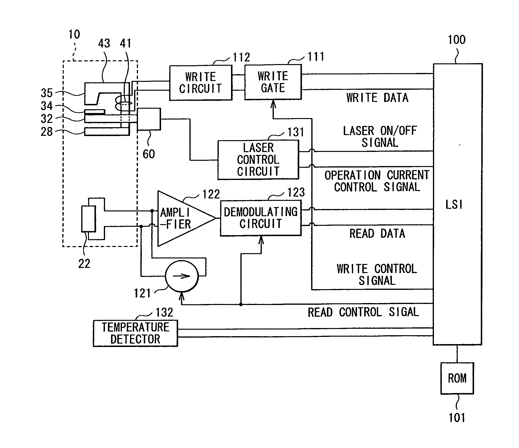
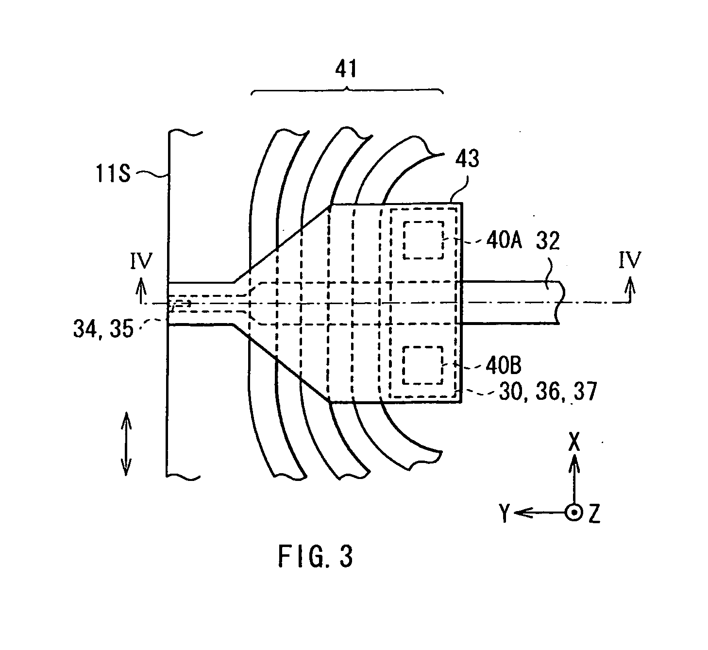
[0013]In the heat-assisted magnetic write head according to an embodiment of the invention, the plasmon generator has the end portion having a minimum thickness in a region close to the waveguide. Therefore, on the air bearing surface, the magnetic pole and the generating position of the near-field light are further approached. On the other hand, the thickness of a portion other than the portion located close to the waveguide is increased to improve the efficiency of heat dissipation of the plasmon generator. Therefore, compared to the case where the end portion of the plasmon generator has a certain thickness, while the efficiency and precision of the heat-assisted magnetic recording are improved, increase of temperature of the magnetic pole and in the vicinity thereof is suppressed, and therefore the corrosion of the magnetic pole and defect in the configuration near the magnetic pole are less likely to occur. As a result, while securing the long-time reliability, the recording operation may be achieved with increased efficiency and stability.
[0014]In the heat-assisted magnetic write head according to an embodiment of the invention, the end portion of the plasmon generator preferably includes, for example, a V-shaped mid-portion including a pointed edge projected toward the waveguide, and a couple of wing portions facing to each other with the mid-portion in between in a direction across write tracks. The magnetic pole is preferably provided to be in contact with the mid-portion of the plasmon generator. Further, the magnetic pole preferably has a width smaller than that of the waveguide and of the mid-portion in the direction across write tracks. When the above-described configuration is applied, distribution of recording magnetic field emitted from the magnetic pole has a steeper shape. As a result, the maximum intensity of the recording magnetic field necessary for information recording is further increased. Moreover, the mid-portion has a minimum thickness at the pointed edge, and the thickness is desirably increased with increasing distance from the pointed edge in the direction across tracks. With such a configuration, the maximum intensity of the recording magnetic field emitted from the magnetic pole is further increased, edge peaks (peaks of recording magnetic field of the magnetic pole in the vicinity of both ends in the direction across tracks) are less likely to occur because an interface between the magnetic pole and the plasmon generator is a smooth curved-surface, and therefore the magnetic flux is suppressed from leaking into the adjacent tracks.

Problems solved by technology

However, increasing the anisotropic energy of the magnetic microparticles leads to increase in the coercivity of the magnetic disk.
As a result, difficulty occurs in the information recording using the existing magnetic head.
However, it is known that the plasmon generator which generates near-field light by direct irradiation of light converts the irradiated light into near-field light with extremely low efficiency.
Therefore, in the plasmon generator, increase of temperature involved with the absorption of heat energy becomes extremely large.
As a result, depending on the humidity condition of the atmosphere, there is a possibility that the main magnetic pole is corroded by moisture in the air.

Method used


Image

  • Heat-assisted magnetic write head, head gimbals assembly, head arm assembly, and magnetic disk device
  • Heat-assisted magnetic write head, head gimbals assembly, head arm assembly, and magnetic disk device
  • Heat-assisted magnetic write head, head gimbals assembly, head arm assembly, and magnetic disk device

Examples


example 1

[0105]In Example 1, the magnetic read write head 10 as the above-described embodiment illustrated in FIGS. 2 to 7 and the like was manufactured according to the manufacturing method described in the above-described embodiment. Here, the dimensional ratio of the components in the ABS 11S were as follows. When the width of the waveguide 32 in X-axis direction was 1 (500 nm), the width of each of the mid-portion C34 and the wing portion W34 of the first portion 34A was 0.7 and 18, the thickness of the lower layer 34L was 0.1, the maximum thickness of the upper layer 34U was 0.4, the maximum width of the magnetic pole 35 was 0.7, the thickness of the magnetic pole 35 was 2, and the distance between the pointed edge 34G and the waveguide 32 in Z-axis direction was 0.07 (refer to FIG. 5).

example 2

[0106]In Example 2, except that having a sectional surface shape illustrated in FIG. 19, the magnetic read write head 10A having the same structure as that of Example 1 was manufactured according to the manufacturing method described in the above-described embodiment. Specifically, in the magnetic read write head 10A, the plasmon generator 34 was configured by only a portion corresponding to the lower layer 34L in the magnetic read write head 10A, and the width of the second layer 352 of the magnetic pole 35 was larger than that of the waveguide 32. More specifically, when the width of the waveguide 32 was 1 (500 nm), the width of the second layer 352 of the magnetic pole 35 was 2. Therefore, the second layer 352 of the magnetic pole 35 was formed to cover also a part of the wing portions W34 of the plasmon generator 34, and the bending portion 34 BN is formed at the interface between the plasmon generator 34 and the magnetic pole 35. In addition, the relative angle θ at the interse...

example 3

[0107]In Example 3, except that having a sectional surface shape illustrated in FIG. 20, the magnetic read write head 10B having the same structure as that of Example 1 was manufactured according to the manufacturing method described in the above-described embodiment. Specifically, in the magnetic read write head 10B, the plasmon generator 34 was configured by only a portion corresponding to the lower layer 34L in the magnetic read write head 10A.

[0108]The magnetic read write heads 10, 10A, and 10B of Examples 1 to 3 thus manufactured were used to perform heat-assisted magnetic recording into a magnetic disk, and the intensity distribution of the recording magnetic field applied to the magnetic disk at that time was examined. The results are illustrated in FIG. 21 and FIG. 22.

[0109]FIGS. 21A to 21C correspond to the magnetic read write head 10, 10A, and 10B of Examples 1 to 3, respectively, and each illustrate the intensity distribution of the recording magnetic field applied to the...


PUM


Abstract

A heat-assisted magnetic write head includes a magnetic pole having an end surface exposed at an air bearing surface, a waveguide extending toward the air bearing surface to propagate light, and a plasmon generator provided between the magnetic pole and the waveguide, and generating near-field light from the air bearing surface, based on the light propagated through the waveguide. The plasmon generator has an end portion exposed at the air bearing surface or located in close proximity to the air bearing surface, the end portion having a minimum thickness in a region close to the waveguide.

Description

BACKGROUND OF THE INVENTION[0001]1. Field of the Invention[0002]The present invention relates to a heat-assisted magnetic write head used in a heat-assisted magnetic recording in which near-field light is irradiated to lower a coercivity of a magnetic recording medium so as to record information, and a head gimbals assembly, a head arm assembly, and a magnetic disk device mounted with the heat-assisted magnetic write head.[0003]2. Description of Related Art[0004]A magnetic disk device in the related art is used for writing and reading magnetic information (hereinafter, simply referred to as information). The magnetic disk device is provided with, in the housing thereof, a magnetic disk in which information is stored, and a magnetic read write head which records information into the magnetic disk and reproduces information stored in the magnetic disk. The magnetic disk is supported by a rotary shaft of a spindle motor, which is fixed to the housing, and rotates around the rotary shaf...

Claims


Application Information

Patent Timeline
IPC IPC(8): G11B13/08
CPCG11B5/314G11B2005/0021G11B5/6088
Inventor AOKI, SUSUMUTANAKA, KOSUKETSUTSUMI, TAKESHIMIYAUCHI, DAISUKEROPPONGI, TETSUYA
Owner TDK CORPARATION
Learn More