Direct generation semiconductor IRCM laser system

a laser system and semiconductor technology, applied in the field of direct generation semiconductor ircm lasers, can solve the problems of reducing the efficiency of the wall plug or total efficiency, the inability to make optimal one-time jam code generated for a particular mid-infrared band, and the system is less reliable, so as to eliminate sequencing or segmentation, reduce the cost, and the effect of time-consuming

Inactive Publication Date: 2012-08-23
BAE SYST INFORMATION & ELECTRONICS SYST INTERGRATION INC
View PDF5 Cites 24 Cited by
  • Summary
  • Abstract
  • Description
  • Claims
  • Application Information

AI Technical Summary

Benefits of technology

[0027]Finally, there is a distinct advantage to having a simultaneously-generated multi-spectral output. For optical parametric oscillator systems, one has to sequence through the various waveform segments to provide optimal Jam Codes for each band. This sequencing is time consuming and results in unacceptably long delays. With direct generation semiconductor lasers, each portion of the multi-spectral output can be generated simultaneously, thus eliminating sequencing or segmentation.
[0028]In summary, what is provided is the utilization of direct generation semiconductor infrared countermeasure lasers which can be independently modulated and combined so as to provide a simultaneously-generated multi-spectral output beam. The countermeasure system is smaller and more lightweight than conventional IRCM laser systems, is less expensive, is non-cryogenically cooled and is configurable for multi-spectral generation with asynchronous jam codes in which the spectral distribution can be customized by combining multiple emitters with a range of center wavelengths. Moreover, architectural simplification via removal of the need for optical pumping increases reliability and reduces cost of the laser unit.

Problems solved by technology

The use of optical parametric oscillators results in a less reliable system with higher weight and complexity.
It will be appreciated that the number of different wavelengths generated in this manner may not all be useful in countermeasuring and thus result in lost energy, which results in reduced wall-plug or total efficiency.
The fact that these jam codes are identical means that the one jam code that is generated cannot be made optimal for a particular mid-infrared band.
When utilizing optical parametric oscillators the challenge is to develop a hybridized generic jam code that addresses all the different bands in which threats operate.
The problem in all optical parametric oscillators is that wavelengths are created in optical-to-optical transmissions along the beam line to get all the beam wavelengths that are required.
The result is either that there is no generalized optimized waveform which is optimally capable of countermeasuring all threats, or one has to cycle through the modulation sequences a number of times.
Typically the missile impacts the target within a few seconds, thus limiting the segmentation durations that are available.
As mentioned above, one of the difficulties in generating collimated light in this fashion is that one requires different optimized jam codes for different threats.
There is a significant disadvantage to using the synchronized code associated with optical parametric oscillators because one cannot produce simultaneous asynchronous optimized codes.
Secondly, having multiple optical-to-optical stages is sub-optimal from an efficiency perspective because of the inherent inefficiency of each stage, manifested by either heat or unused optical radiation that is produced outside the desired spectral range.
Additionally, due to the heat production, many of the optical parametric oscillators are cryogenically cooled, which is expensive and failure prone.
Moreover, reliability as well as complexity makes optical parametric oscillator systems less desirable.
Another problem with the present DIRCM systems is the ability to be able to tailor the spectral content of the outgoing beam to be optimal for a number of different bands.
With optical parametric oscillators the color temperature ratio is not easily adjustable.
Nor is it possible with current DIRCMs to customize a spectral distribution by combining multiple emitters with a range of center wavelengths, and presently this is not done.

Method used


Image

  • Direct generation semiconductor IRCM laser system
  • Direct generation semiconductor IRCM laser system
  • Direct generation semiconductor IRCM laser system

Examples


Embodiment Construction

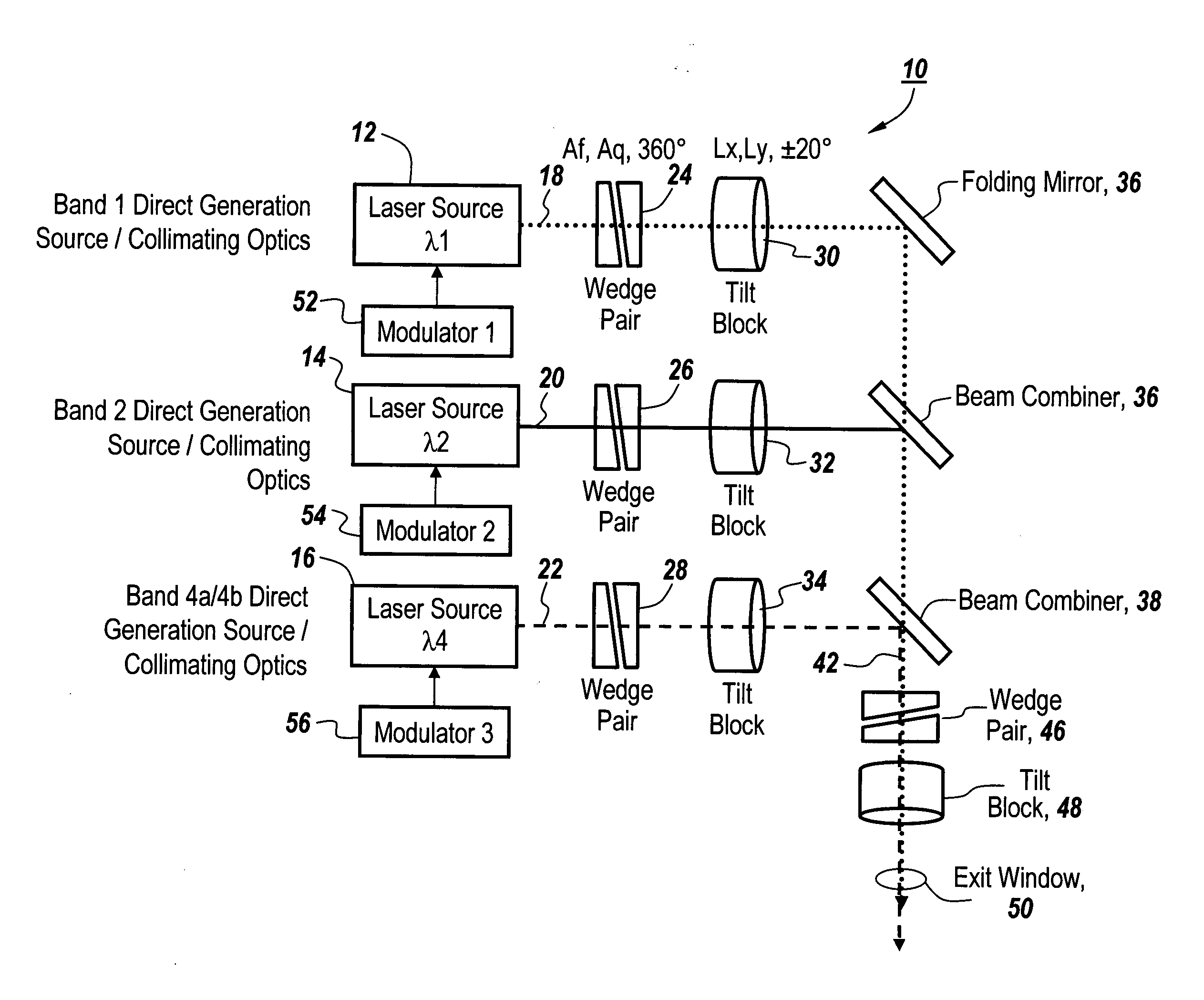
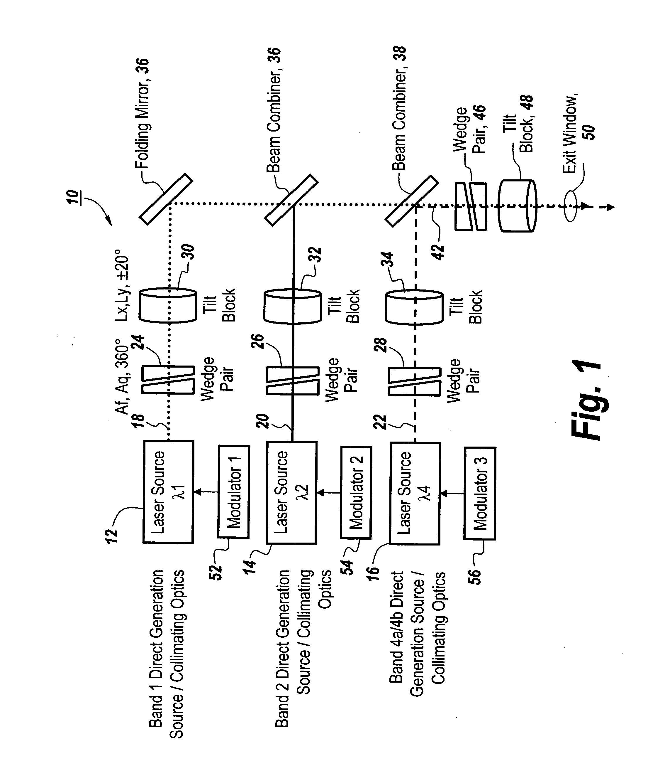
[0035]Referring now to FIG. 1, in a direct generation semiconductor DIRCM laser system 10 a number of direct generation laser sources 12, 14 and 16 utilize collimated optics to provide beams 18, 20 and 22 through respective wedge pairs 24, 26 and 28. In one embodiment, the wedge pairs are Risley prisms. The outputs from wedge pairs 24, 26 and 28 are respectively coupled through tilt blocks 30, 32 and 34 and impinge respectively on a folding mirror 36, a beam combiner 38 and another beam combiner 40. The result is an output beam 42 with jam code applied that passes through another wedge pair 46 and another tilt block 48 and out through an exit window 50.

[0036]Each of the laser sources 12, 14 and 16 is provided with independent jam code modulation by respective modulators 52, 54 and 56. Each of the modulators independently and asynchronously modulates the output of the associated laser source such that the modulation on laser beams 18, 20 and 22 may be specifically tailored for a part...


PUM


Abstract

Direct generation semiconductor infrared countermeasure lasers are provided that can be independently modulated and combined so as to provide a simultaneously-generated multi-spectral output for the beam. The countermeasure system is smaller and more lightweight than conventional IRCM laser systems, is less expensive, is non-cryogenically cooled and is configurable for multi-spectral generation with asynchronous jam codes in which the spectral distribution can be customized by combining multiple emitters with a range of center wavelengths.

Description

FIELD OF THE INVENTION[0001]This invention relates to infrared countermeasures utilizing lasers and more particularly to the utilization of a direct generation semiconductor IRCM laser in which infrared energy is directly generated and in which separate semiconductor lasers operating in different energy bands provide the opportunity for optimal simultaneously generated waveforms for each band to defeat threats in shorter timelines with independent intensity control of band outputs for spectral distribution control.BACKGROUND OF THE INVENTION[0002]Infrared countermeasure systems historically have involved wide field of view broadband jammers that use plasma discharge lamps or hot glowing heat element lamps and disperse energy in a wide area. These types of systems are being replaced with directed energy systems involving pointed lasers, with these systems being known as directed IR countermeasures or DIRCM systems[0003]The lasers utilized in these systems have typically involved gas ...

Claims


Application Information

Patent Timeline
Patent Type & Authority Applications(United States)
IPC IPC(8): H04K3/00G21K5/00G01S17/87
CPCH04K3/42H04K3/43H04K2203/14F41H13/0056G01S7/4815F41G7/224G01S7/495G01S17/87F41H11/02
Inventor CHAO, CHRISTOPHER J.
Owner BAE SYST INFORMATION & ELECTRONICS SYST INTERGRATION INC
Why Eureka
Try Eureka