

Conductive connecting material and method for connecting terminals using the same
a technology which is applied in the field of connecting material and connecting terminal using the same, can solve the problems of insufficient insulation between adjacent terminals, difficulty in coping with terminals at narrower pitch, and conventional anisotropic conductive adhesives and films, etc., and achieves high reliability, good electric connection, and easy aggregate
- Summary
- Abstract
- Description
- Claims
- Application Information
AI Technical Summary
Benefits of technology
Problems solved by technology
Method used
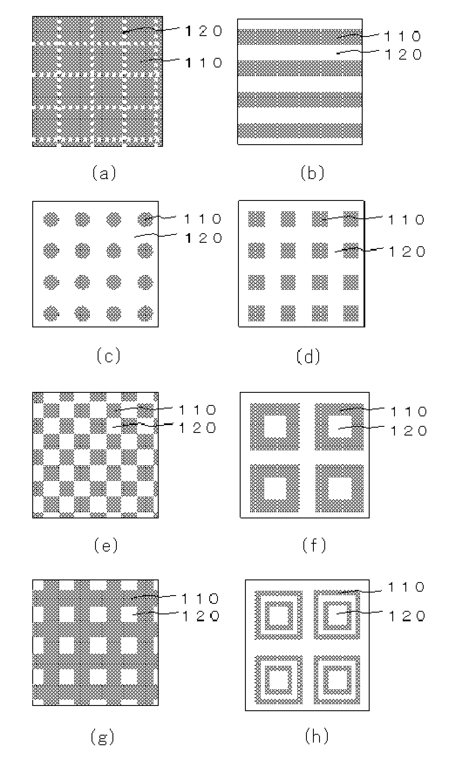
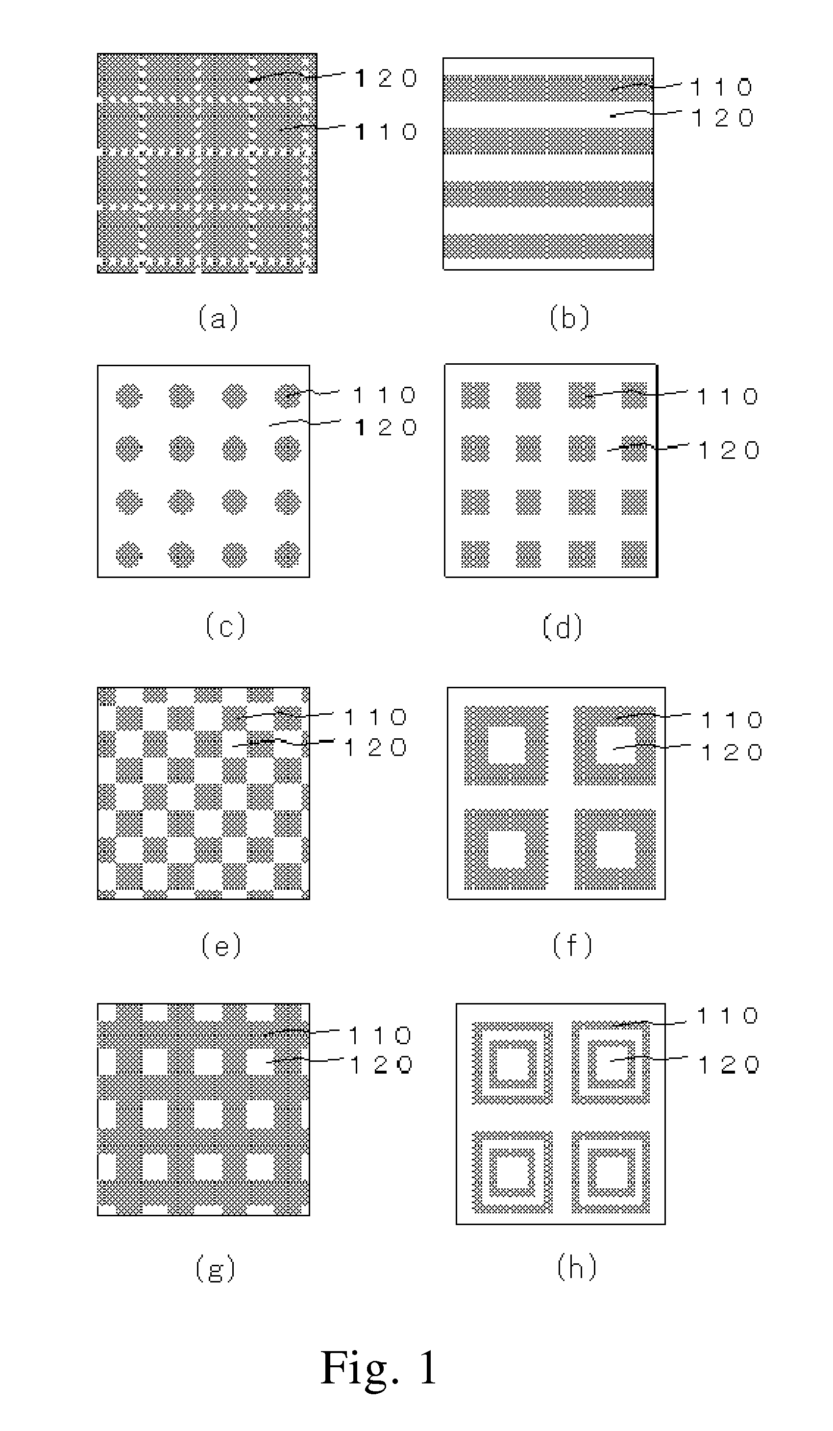
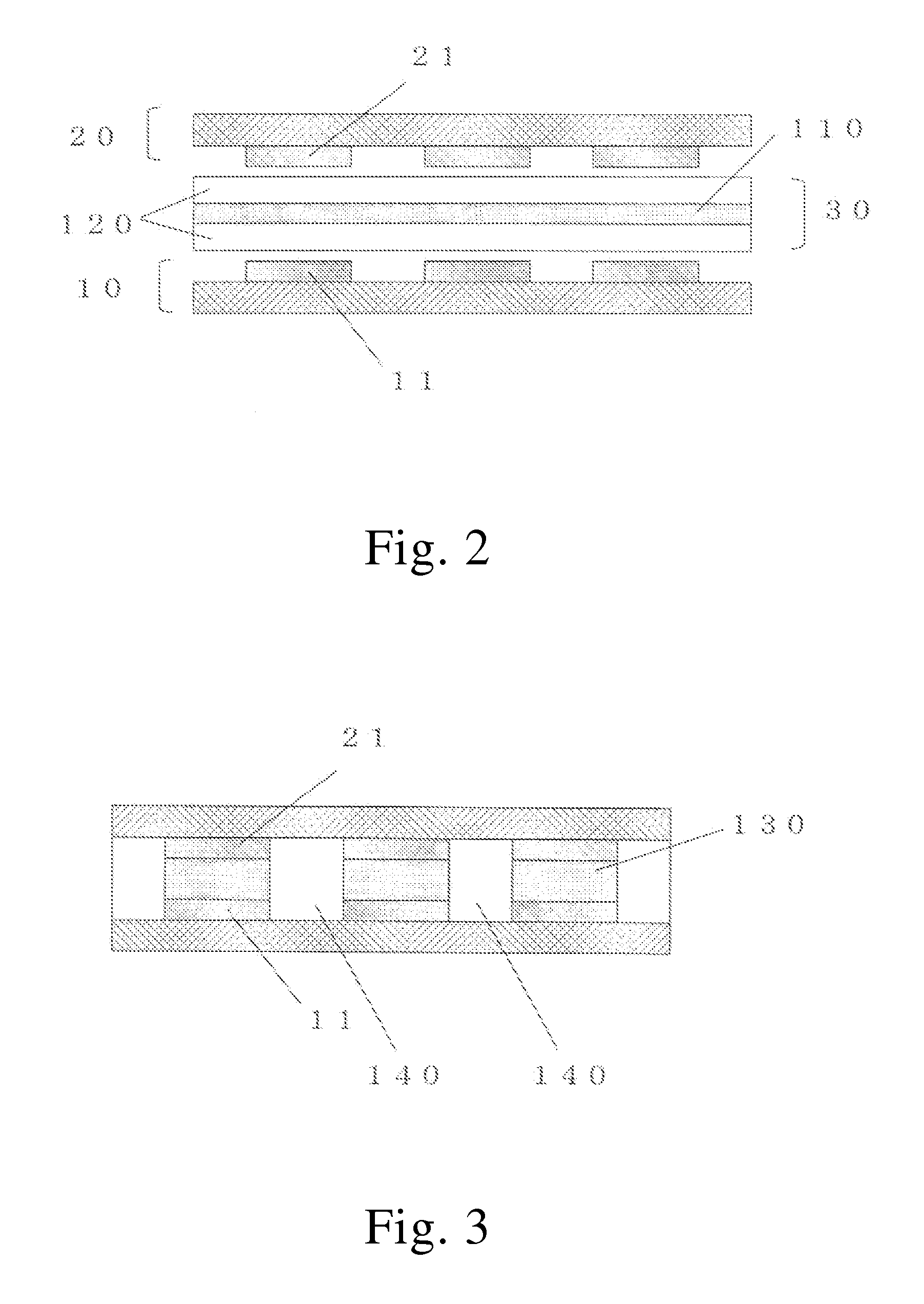
Image

Examples
examples
[0169]Hereinafter, the present invention will be described by way of examples, although the present invention should not be limited to the following examples.
examples 1-4
(1) Preparation of Curable Resin Composition
[0170]The components shown in Table 1 were dissolved in methylethyl ketone (MEK) to obtain a varnish of a resin composition having a solid content of 40%. The obtained varnish was applied onto a polyester sheet with a comma coater, and dried at 90° C. for 5 minutes to obtain two sheets of film-like curable resin composition with a thickness shown in Table 1.
[0171](2) Production of Conductive Connecting Material
[0172]The resulting film-like curable resin composition was laminated on both sides of the solder foil having a thickness shown in Table 1 under the conditions of 60° C., 0.3 MPa and 0.3 m / min to produce a conductive connecting material.
[0173]The volume ratio ((A) / (B)) of the resin composition (A) and the metal foil (B) was derived as follows and shown in Table 1.
Volume ratio((A) / (B))=(S(B)−S) / (S−S(A))
[0174]S: Specific gravity of conductive connecting material
[0175]S(A): Specific gravity of resin composition
[0176]S(B): Specific gravi...
example 5
[0183]A curable resin composition having the thickness shown in Table 1 was prepared in the same manner as Examples 1-4. The resulting film-like curable resin composition was laminated on both sides of a frame-like solder foil having the thickness shown in Table 1, inner dimension of 8 mm×8 mm and outer dimension of 10 mm×10 mm under the conditions of 60° C., 0.3 MPa and 0.3 m / min to provide a conductive connecting material.
[0184]The volume ratio ((A) / (B)) of the resin composition (A) and the metal foil (B) was determined according to the above-described method and shown in Table 1. In addition, the resulting conductive connecting material was used for terminal-to-terminal connection of the substrates in the same manner as Examples 1-4 (method described in “(3) Terminal-to-terminal connection” above) except that the substrate used consisted of FR-4-based material (thickness: 0.1 mm) and a circuit layer (copper circuit, thickness: 12 um), which had a row of connection terminals forme...
PUM
| Property | Measurement | Unit |
|---|---|---|
| melting point | aaaaa | aaaaa |
| volume ratio | aaaaa | aaaaa |
| adhesion area | aaaaa | aaaaa |
Abstract
Description
Claims
Application Information